
Operating Instructions
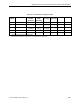
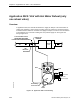
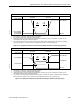
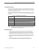
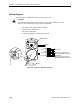
Table Of Contents
- Table of Contents
- How To Use This Manual
- Chapter 1—Hardware
- Chapter 2—Applications for ATEC— Base VAV
- Chapter 3—Applications for ATEC—VAV with Reheat
- Chapter Overview
- Introduction
- Application 2500: VAV Cooling Only
- Application 2501: VAV Cooling or Heating
- Application 2522: VAV with Electric Reheat or Baseboard Radiation
- Application 2523: VAV with Hot Water Reheat (only one reheat valve)
- Application 2524: VAV Series Fan Powered with One Stage of Electric Reheat
- Application 2526: VAV Parallel Fan Powered with One Stage of Electric Reheat
- Application 2473: Slave Mode
- Chapter 4—Point Database
- Chapter 5—Troubleshooting
- Glossary
- Index

Chapter 3—Applications for ATEC—VAV with Reheat
3-46 Siemens Building Technologies, Inc.
Sequencing Logic (Optional)
The settings of FLOW START (Point 16), FLOW END (Point 17), REHEAT START (Point 22),
and REHEAT END (Point 23) determine how the damper and reheat modulation are
sequenced while in heating mode. These points represent the values of HTG LOOPOUT
(Point 80) at which modulation of the damper and reheat begin and end.
The damper moves from minimum position to fully open as HTG LOOPOUT increases from
FLOW START to FLOW END. If FLOW START and FLOW END are both set to 0% (default
value), the damper stays at minimum position while in heating mode.
The heating valve moves from fully closed to fully open as HTG LOOPOUT increases from
REHEAT START to REHEAT END. Default values for these points are 0% and 100%
respectively. See Hot Water Reheat (page 3-45) for more information.
By varying the values of these start and end points, the damper and the reheat can be
sequenced in series, parallel, or overlapping, as shown in the following table:
Series Parallel Overlapping Minimum Flow
(Default Value)
FLOW START 0% 0% 0% 0%
FLOW END 50% 100% 75% 0%
REHEAT START 50% 0% 25% 0%
REHEAT END 100% 100% 100% 100%
Calibration
Air Velocity Sensor—Calibration of the controller’s internal air velocity sensor is periodically
required to maintain accurate air velocity readings. CAL SETUP (Point 95) is set with the
desired calibration option during controller startup. Depending on the value of CAL SETUP,
calibration may be set to take place automatically or manually. If CAL AIR (Point 94) is set to
YES, calibration is in progress. The damper is commanded closed to get a zero airflow
reading during calibration.
Hot Water Valve—Calibration of a hot water valve is done by commanding the valve to
closed.
At the end of a calibration sequence, CAL AIR automatically returns to NO. A setting of NO
indicates that the controller is not in a calibration sequence.
Fail-Safe Operation
If the air velocity sensor fails, the controller uses pressure-dependent control. The
temperature loop controls the operation of the damper.
If the room temperature sensor fails, the controller operates using the last known temperature
value.