
Operating Instructions
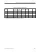
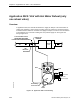
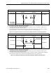
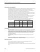
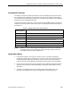
Table Of Contents
- Table of Contents
- How To Use This Manual
- Chapter 1—Hardware
- Chapter 2—Applications for ATEC— Base VAV
- Chapter 3—Applications for ATEC—VAV with Reheat
- Chapter Overview
- Introduction
- Application 2500: VAV Cooling Only
- Application 2501: VAV Cooling or Heating
- Application 2522: VAV with Electric Reheat or Baseboard Radiation
- Application 2523: VAV with Hot Water Reheat (only one reheat valve)
- Application 2524: VAV Series Fan Powered with One Stage of Electric Reheat
- Application 2526: VAV Parallel Fan Powered with One Stage of Electric Reheat
- Application 2473: Slave Mode
- Chapter 4—Point Database
- Chapter 5—Troubleshooting
- Glossary
- Index

Application 2523: VAV with Hot Water Reheat (only one reheat valve)
Siemens Building Technologies, Inc. 3-47
Automated Checkout
The ATEC has a built-in checkout procedure that can be manually initiated at any time after
the controller has been installed. The procedure tests all of the necessary I/O and ensures
the controller has the ability to operate within the set airflow range, between CLG FLOW MIN
(Point 31) and CLG FLOW MAX (Point 32).
To perform the checkout procedure, set CHK OUT (Point 10) to YES. When the procedure is
completed, CHK OUT returns to NO and the results are displayed in CHK STATUS (Point 3).
See Table 3-7.
Table 3-7. Possible Failure Value and Description.
CHK STATUS
Values (Point 3)
Description
-1 Checkout procedure has not been run since last controller initialization.
0 No errors found.
1 Room temperature sensor failed.
2 Room setpoint dial failed [If STPT DIAL (Point 14) is set to YES].
4 Air velocity sensor failed.
8 Controller could not reach CLG FLOW MIN or below.
16 Controller could not reach CLG FLOW MAX or above.
NOTE: Multiple failures are added together and displayed as one value. For example, if
the room temperature sensor failed (1) and the controller could not reach CLG
FLOW MAX (16), CHK STATUS displays 17.
Application Notes
1. If temperature swings in the room are excessive or there is trouble maintaining the
setpoint, the cooling loop, the heating loop, or both need to be tuned. If FLOW (Point 75)
is oscillating while FLOW STPT (Point 93) is constant, the flow loop requires tuning.
Contact your local Siemens Building Technologies representative for more information.
2. In order for the heating loopout to work, MTR2 must be enabled by setting MTR SETUP
(Point 58). Contact your local Siemens Building Technologies representative for more
information.
3. The ATEC, as shipped from the factory, keeps all associated equipment off. The
controller and its equipment are released to application control during start-up.