
User Manual


3 / 14
Siemens Electromotoric actuators CB1N4520en
Smart Infrastructure 2019-10-16
Equipment combinations
Electromotoric Actuators
1)
SQL321B25
SQL361B25
SQL351B25
SQL321B50
SQL361B50
SQL351B50
SQL321B150
SQL361B150
SQL351B150
SQL321B270
SQL361B270
SQL351B270
SQL321B570
SQL361B570
SQL351B570
SQL321B1400
SQL361B1400
SQL351B1400
SQL321B2650
SQL361B2650
SQL351B2650
Butterfly Valve Dp
s
[kPa]
VKF42.50 700
VKF42.65 700
VKF42.80 700
VKF42.100 700
VKF42.125 700
VKF42.150 700
VKF42.200 700
VKF42.250 700
VKF42.300 700
VKF42.350 700
VKF42.400 700
VKF42.450 700
VKF42.500 700
VKF42.600 700
1)
SQL321B.., SQL361B.. SQL351B.. electromotoric actuators can be mounted directly on VKF42.. butter-
fly valves.
Dp
s
Maximum permissible differential pressure at which the motorized butterfly valve will close securely
against the pressure (close off pressure)
Mechanical design
The actuator is driven by a 2-position (SPDT) or DC 0…10 V, 4…20 mA control signal
from the controller and generates a rotary motion which is transferred to the butterfly
valve via a driver.
These electromotoric actuators require no maintenance. They have a reversible
asynchronous motor which drives the main shaft via gear train, which accommodates
the diagonal square head of the butterfly valve. For SQL321B25, the coil spring is
fitted with handwheel shaft, handwheel is engaged when pushed in. For others, the
worm shaft is fitted with a direct-acting handwheel.
The actuators are 90° rotated so as to work with Siemens VKF42.. butterfly valves.
During automatic operation, rotation is stopped by two built-in end-switches.
To prevent the temperature inside the housing from falling below the dew point tem-
perature, the actuators are equipped with a built-in heating element.
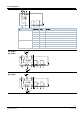
1 Position indication
2 Terminal compartment
3 Cover (motor inside)
4 Handwheel
5 EN ISO 5211 flange connection