Acvatix™ Electromotoric actuators SAX..Y, SAL..
Siemens Switzerland Ltd Industry Sector Building Technologies Division Gubelstrasse 22 6301 Zug Switzerland Tel. +41 41 724 24 24 www.siemens.com/sbt © 2013 Siemens Switzerland Ltd Subject to change 2 / 62 Siemens Building Technologies Electromotoric actuators SAX..Y, SAL..
Contents 1 About this documentation...................................................................... 5 1.1 Navigation / Quick access......................................................................... 5 1.2 Revision history ......................................................................................... 5 1.3 Reference documents ............................................................................... 6 1.4 1.4.1 1.4.2 1.4.3 1.4.4 Before you start ..........................
.2 Modulating control ................................................................................... 37 4.3 4.3.1 4.3.2 Function module AZX61.1 ....................................................................... 38 Sequence control (signal adaptation) ..................................................... 38 Changeover of acting direction ............................................................... 39 4.4 Positioning signal and flow characteristic selection ................................
1 About this documentation 1.1 Navigation / Quick access Information about a specific actuator is provided throughout the document. The structure of chapters 2 to 4 is as follows: Quick access to important information including reference to pages: 2 Engineering Product no. Equipment combinations 3 Handling Accessories SAX31.00Y Page 10 Page 13 Page 31 SAX81.00Y SAX81.03Y SAL31.00T10 SAL31.03T10 SAL61.00T10 SAL61.03T10 Accessories (mounting) - SAX31.03Y SAX61.
1.3 Reference documents Type of document SAX..Y Data Sheet N4515 N4502 ASK31N: ASK33N: Mounting Instructions CE Declaration of Conformity Environmental Declaration AC 230 V AC/DC 24 V 1.4 Before you start 1.4.1 Trademarks ASC..: ASZ7.5/..: AZX61..: ASK39..: ASZ6.6: T4501X1 T4501X2 SAL.. M4040.1 M4040.2 M4040.3 M4040.3 M4501.1 M4502.1 M4502.2 T4502X1 T4502X2 E4502 The table below lists the third-party trademarks used in this document and their legal owners.
1.4.4 Document use / request to the reader Before using our products, it is important that you read the documents supplied with or ordered at the same time as the products (equipment, applications, tools etc.) carefully and in full. We assume that persons using our products and documents are authorized and trained appropriately and have the technical knowledge required to use our products as intended.
2 Engineering 2.1 Product description The line of large actuators is comprised of stroke actuators SAX..Y and rotary actuators SAL... Mechanical design 1 User interface and electrical connections 2 Power transmission and preparation 3 Yoke (for assembly of actuator and seat, slipper or butterfly valve) Components Page 2.
Product no. Stock no. SAX31.00Y S55150-A105-A998 SAX31.03Y S55150-A106-A998 SAX61.03Y S55150-A100-A998 SAX81.00Y S55150-A102-A998 SAX81.03Y S55150-A103-A998 2.3 Type summary 2.3.1 Stroke actuators Stroke 20 mm Stock no. SAL31.00T10 S55162-A108 SAL31.03T10 S55162-A109 SAL61.00T10 S55162-A100 SAL61.03T10 S55162-A101 SAL81.00T10 S55162-A104 SAL81.03T10 S55162-A105 Ang. rot.
Typical applications Heating plants Ventilation and air conditioning plants Heat generation Heat distribution District heating plants Valves Valves PN6 -10…100 °C PN10 -10…100 °C PN16 -10…100 °C PN16 -10…100 °C PN16 -25…100 °C 2.5 Equipment combinations 2.5.1 Stroke actuators − 3-port valves Stroke actuators SAX..Y Basic Doc. P4030 Data Sheet Valve type 1) N4410 VXF21.22...25 2) VXF21.25.. VXF21.39-40 2) VXF21.40-.. VXF21.50 VXF21.50-40 VXF21.65 VXF21.65-63 VXF21.80-78 VXF21.
2.5.2 Typical applications Heating plants Ventilation and air conditioning plants Heat generation Heat distribution District heating plants Valves Valves PN6 -10…100 °C PN10 -10…100 °C PN16 -10…100 °C PN16 Stroke actuators − 2-port valves Stroke actuators SAX..Y Basic Doc. P4030 Data Sheet Valve type 1) N4310 VVF21.22...25 2) VVF21.25-.. VVF21.39-40 2) VVF21.40-.. VVF21.50 VVF21.50-40 VVF21.65 VVF21.65-63 VVF21.80-78 VVF21.80-100 2) N4320 VVF31.15-.. 1) VVF31.24...25 2) VVF31.25-.. 1) VVF31.
2.5.3 Typical applications Heating plants Ventilation and air conditioning plants Heat generation Heat distribution District heating plants Slipper valves PN6 1 °C...120 °C Butterfly valves PN16 -10 °C…120 °C Rotary actuators SAL..T10 Data Sheet Valve type N4241 VBF21.40 Rotary actuators – slipper and butterfly valves Angular rotation Torque Data Sheet N4502 3 DN kvs [m /h] 40 25 - - 1) VBF21.50 50 40 - - 1) VBF21.65 65 63 ASK31N VBF21.80 80 100 ASK31N VBF21.
2.6 Accessories 2.6.1 Electrical accessories Auxiliary switch ASC10.51 Product no. Stock no. SAX31..Y SAX61..Y SAX81..Y SAL31.. SAL61.. SAL81.. S55845-Z103 Max. 2 Max. 2 1) Stock no. SAX..Y SAL.. S55845-Z104 (ASZ7.5/135) S55845-Z105 (ASZ7.5/200) S55845-Z106 (ASZ7.5/1000) Max. 2 Max. 1 Max. 1 Max. 1 Max. 1 Function module AZX61.1 Stem heating element ASZ6.6 S55845-Z107 S55845-Z108 Max. 1 Max. 1 AZX61.1 - Max. 1 - - Available with 135 Ω, 200 Ω or 1000 Ω 2.6.2 Product no.
2.7 Product replacements Replacement of SQX.. / SQL.. actuators by SAX..Y / SAL.. actuators. When replacing actuators consider positioning force, torque and positioning times. Adjust in the controller the parameter "Running time" respectively "Positioning time", to ensure stable control. The replacement of accessory items needs to be taken into consideration also. In that case, compatibility is not necessarily ensured. Note 2.7.1 SQX.. SQX31.. SQX61.. SQX81.. SQX32.. SQX62.. SQX82..
Rotary actuators SQL.. 1) VBF21.. VBF31.. B3f.. C1f.. K1i.. K1f.. VKF41.. DN 40 / DN 50 DN 65…150 1) DN 40 / DN 50 DN 65…100 1) DN 40 / DN 50 DN 65…150 1) DN 40 / DN 50 DN 65…100 DN 20…32 DN 40…200 DN 40…125 DN 150 / DN 200 SQL31.. Direct Direct Direct Direct Direct Direct 1) SQL32.. ASK25 ASK25 ASK24 ASK24 - SQX.. Stem heater 1 auxiliary switch, 1 potentiometer (1000 Ω) Double auxiliary switch Auxiliary switch SQX31.. SQX81.. ASZ6.5 SQX61.. ASZ6.5 SQX32.. SQX82.. ASZ6.5 SQX62.. ASZ6.5 ASZ7.
2.8 Spare parts The following spare part sets are available: SAX..Y Stock number 8000060843 Housing cover Screw (valve stem coupling) U-bracket Single components from the spare part sets are not available. SAL.. Stock number 8000060844 Housing cover 2 adapters 1 pc. 14 mm 1 pc. 11 mm 4 screws 2 pcs. M5 x 20 mm 2 pcs. M6 x 20 mm Single components from the spare part sets are not available. 16 / 62 Siemens Building Technologies Electromotoric actuators SAX..Y, SAL..
2.9 Sizing 2.9.1 Parallel operation of actuators SA..31.. and SA..81.. 3-position actuators must have one specific controller each, refer to "Connection diagrams" (page 54). SA..61.. Up to 10 actuators can drive in parallel on a controller output with a rating of 1 mA. Modulating actuators have an input impedance of 100 kΩ. 2.9.
The following diagram can be used to determine the cable lengths and wire crosssectional areas. Cable length L L/P-diagram for AC/DC 24 V Power Consumption P Permissible cable length L as a function of power P and cross-sectional area of wire as a parameter Note Formulas for wire lengths P is the decisive power consumption of all actuators connected in parallel. When operating on AC 24 V, power consumption is in VA; when operating on DC 24 V, in W.
3 Handling 3.1 Mounting and installation 3.1.1 Mounting positions Indoor use Outdoor use 1) 1) Only in connection with weather shield ASK39.1 19 / 62 Siemens Building Technologies Electromotoric actuators SAX..Y, SAL..
3.1.2 Fitting stroke actuators to seat valves VVF.. / VXF.. or VVG.. / VXG.. First, observe "Mounting positions" (page 19). 1 Actuator’s stem retracted 3 5 2 4 10 mm 7 6 8 10 mm 20 / 62 Siemens Building Technologies Electromotoric actuators SAX..Y, SAL..
3.1.3 Fitting rotary actuators to butterfly valves VKF41.. First, observe "Mounting positions" (page 19). Scope of delivery Mounting set ASK33N Mounting set (2 parts) 1 adapter inc. fixing screw 5 screws 1 adapter 4 pcs. M6 x 16 mm 1 pc. M5 x 20 incl. nut Note Actuators SAL.. are not compatible with mounting sets ASK31, ASK32, ASK33, ASK35, ASK40, and ASK41. 1 2 5 mm 3 5 mm 21 / 62 Siemens Building Technologies Electromotoric actuators SAX..Y, SAL..
4 12 mm 6 5 5 mm 7 4 mm 1) 1) Angle position errors between actuator shaft and valve stem must be corrected via manual control (refer to "Manual adjuster" page 46). 3.1.4 Fitting rotary actuators to slipper valves VBF21.. First, observe "Mounting positions" (page 19). Scope of delivery Mounting set ASK31N Mounting set (2 parts) 5 screws 1 adapter inc. fixing screw 1 adapter 4 pcs. M6 x 16 mm 1 pc. M5 x 20 mm incl. nut 22 / 62 Siemens Building Technologies Electromotoric actuators SAX..
SAL..T10 rotary actuators only fit on VBF21.., DN65…150. For VBF21.., DN40/50 use SQK34.., SQK84.. or SQK33.00 rotary actuators. With VBF21.. (e.g. DN 125), the following steps must be performed prior to fitting the mounting set. 1 Opening counterclockwise 3a 2 4 mm, 5 mm 12 mm 3b 4 mm, 5 mm 12 mm 23 / 62 Siemens Building Technologies Electromotoric actuators SAX..Y, SAL..
Opening clockwise 3c 4 mm, 5 mm 12 mm 3d 4 mm, 5 mm 12 mm For further mounting positions of VBF 21.. and routing of the connection cables the rotary actuators and adapters must be mounted according to the sketches above. 3.1.5 Special notes on mounting Accessories Before fitting the accessory items shown below, the following steps must be performed: 1. Actuator is mechanically connected to a Siemens valve. 2. Observe compatibility and choice of combinations. Refer to "Accessories" (page 13). 3.
1 2 PZ 2 Plug-in space for… Interior view of setting elements and plug-in spaces Potentiometer ASZ7.5/.., or B Function module AZX61.1 , or C LED D DIL switches E Calibration slot F Connection terminals A Auxiliary switch ASC10.51 Plug-in space for… Potentiometer ASZ7.5/.. 1 potentiometer ASZ7.5/.. Auxiliary switch ASC10.51 Scope of delivery 1 screw 2 screw covers 1 pc. First, observe "Special notes on mounting" (page 24).
5 Turn to 0% 6 7 Function module AZX61.1 No.: 2 8 Observe "Wiring" (page 30) Observe "Connection terminals" (page 53) First, observe "Special notes on mounting” (page 24). 1 2 Set function module (page 38) Nr.: 3 Plug-in space B 3 Auxiliary switch ASC10.51 4 1 auxiliary switch ASC10.51 Scope of delivery 1 screw 2 screw covers 1 pc. 26 / 62 Siemens Building Technologies Electromotoric actuators SAX..Y, SAL..
Plug-in space A First, observe "Special notes on mounting" (page 24). Fit the screw covers first- otherwise danger of life! 1 2 3 4 5 Adjust switch position (refer also to "Manual operation" page 46) 6 No.:1 When initial situation: ∞ Ω When initial situation: 0 Ω 7 No.: 1 Observe "Wiring" (page 30) 8 Observe "Connection terminals" (page 53) 27 / 62 Siemens Building Technologies Electromotoric actuators SAX..Y, SAL..
Plug-in space B First, observe "Special notes on mounting" (page 24). First, fit the screw covers – otherwise danger of life! 1 2 3 4 5 Adjust switch position (refer also to "Manual operation" page 46) 6 No.: 1 When initial situation: 0 Ω 7 No.: 1 Observe "Wiring" (page 30) When initial situation: ∞ Ω 8 Observe "Connection terminals" (page 53) 28 / 62 Siemens Building Technologies Electromotoric actuators SAX..Y, SAL..
Scope of delivery Stem heating element ASZ6.6 1 stem heating element ASZ6.6 1 screw 1 pc. M4 x 30 incl. nut When fitting the stem heating element, stroke actuator and valve must be assembled. The stem heating element is powered separately. First, observe "Special notes on mounting” (page 24). 1 10 mm 2 14 mm 3 Weather shield ASK39.1 4 8 mm First, observe "Special notes on mounting” (page 24). Scope of delivery Weather shield ASK39.
3.1.6 Wiring (installation) Conduct the electrical connections in accordance with local regulations on electrical installations as well as the "Connection diagrams" on page 53. Preparation of wire endings The cable endings must be prepared before as follows.
Auxiliary switch ASC10.51 1 2 No.: 4 and Potentiometer ASZ7.5/.. 3 Mechanically 4 Observe "Connection terminals" (page53) 3.2 Commissioning and operation 3.2.1 Function check and Calibration Before making the function check, the following preconditions must be satisfied: "Environmental conditions" specified in chapter "Technical data" (page 50) Actuator is mechanically connected to a Siemens valve Actuator is in "Manual operation" mode (page 46).
SA..61.. Calibration is required with modulating actuators and SA..61.. before the function check. General notes on calibration Before making the calibration, the following preconditions must be satisfied: A description of the calibration function is given in chapter "Calibration" (page 41). Housing cover is removed (step 6 "Special notes on mounting", page 24). 1 Bridge contact 2 Check LED (page 47) If required, calibration can be repeated any number of times.
Auxiliary switch ASC10.
3.2.2 Maintenance The actuators are maintenance-free. 3.2.3 Disposal The products contain electrical and electronic components and must not be disposed of together with domestic waste. This applies in particular to the printed circuit board. Legislation may demand special handling of certain components, or it may be sensible from an ecological point of view. Observe all local and currently valid legislation. 34 / 62 Siemens Building Technologies Electromotoric actuators SAX..Y, SAL..
4 Functions and control 4.1 3-position control A 3-position signal drives the actuator via connection terminals Y1 or Y2. The required position is transferred to the valve.
The specified positioning times refer to the respective nominal stroke / nominal angular rotation. Since the end positions of rotary actuators are inside the actuator, the following remarks refer to stroke actuators. The resulting effective strokes vary, depending on the type of valve, resulting in shorter or longer actuator positioning times. Stroke of valve-actuator combination [mm] Positioning times stroke model Positioning time [sec] Legend diagram A B A…B Notes Mechanical end position in SAX..
4.2 Modulating control The modulating positioning signal drives the actuator steplessly. The positioning signal range (DC 0...10 V / DC 4...20 mA, 0...1000 Ω) corresponds in a linear manner to the positioning range (fully closed...fully open, or 0…100 % stroke).
4.3 DIL switches Acting direction OFF ON 1) 1) 1) Sequence control Direct acting positioning signal Y or Z Sequence control not active Reverse acting positioning signal Y or Z Sequence control (signal adaptation) Factory setting: All switches set to OFF 4.3.1 DIL switches Sequence control (signal adaptation) Sequence control ON 1) HEX switches Function module AZX61.1 1) Sequence control (signal adaptation) Factory setting: All switches set to OFF Nr.
Examples Legend diagram A B C H 4.3.
4.4 Positioning signal and flow characteristic selection DIL switches Positioning signal Y OFF ON 1) 1) Position feedback U Flow characteristic DC 0…10 V DC 0…10 V log = equalpercentage DC 4…20 mA DC 0…10 V lin = linear Factory setting: All DIL switches set to OFF Ω Actuator Flow characteristic Valve Totally log lin Y, Z H V Positioning signal Stroke Volumetric flow Acting direction: Direct Acting direction: Reverse 40 / 62 Siemens Building Technologies Electromotoric actuators SAX.
4.5 Acting direction and flow characteristic The selection of changeover of acting direction and characteristic with the DIL switches depends on the type of actuator (with or without fail safe function) and the associated type of valve (valve characteristic, push to open, pull to open). When the positioning signal increases (DC 0…10 V, DC 4…20 mA, 0...
Actuator Positioning signal Y, Z Actuator Position feedback U Direct acting Reverse acting Y, Z H U 4.7 Positioning signal Stroke Position feedback Acting direction: direct Acting direction: reverse Calibration To match the actuator to production-related mechanical tolerances of the individual valves, accurate positioning and position feedback must be ensured, if calibration is performed when the plant is commissioned (page 31).
4.8 Signal priorities The actuators are controlled via different interlinked positioning signal paths (positioning signal “Y“, forced control input “Z“, manual adjuster).
4.10 Detection of foreign bodies The actuator detects when the valve is clogged and adjusts its operational behavior accordingly to prevent damage to itself or the valve. If the actuator hits an obstacle within the calibrated stroke and is not able to overcome it with its nominal positioning force, it stores the position at which the obstacle was hit.
Function principle 4.12 Technical and mechanical design 4.12.1 Transmission of power Incoming positioning signals are translated to positioning commands for the motor. A gear train transmits the motor’s positioning steps to the output stage (valve coupling). Attached to the gear train are the electrical and mechanical accessory items and the manual adjuster. In the case of the rotary actuators, the adjustment to the required torque is made in the output stage.
4.12.2 Coupling SAX..Y SAL.. The stem coupling (1) and neck coupling (2) ensures full backward compatibility with all types of Siemens large-stroke valves produced since 1975. Mounting sets are available for use with butterfly and slipper valves. 4.12.3 Manual adjuster Automatic When the motor drives the manual adjuster turns. Thus in automatic mode, the manual adjuster is used for indication of travel.
4.12.4 Indicators A Indication of travel B Scale Position indication C Indicator D LED Status indication Operational status indication In Automatic mode, the manual adjuster serves for the indication of travel. See "Automatic" (page 46). Position indication Position indication is on 2 opposite sides. When turning the manual adjuster, the indicator moves in the same direction. The scale indicates the stroke. When reaching the stops, the valve is either fully open or fully closed.
4.12.5 Auxiliary switch ASC10.51 Electrical accessories The auxiliary switch ASC10.51 switches on or off when a certain position is reached. The switching point can be set between 0…100%. Switching point for S1–S2 and S1–S3 cannot be set separately. If S1–S2 is open then S1–S3 is closed. Adjustable switching point Application example: When using an auxiliary switch, position feedback can trigger an automatic stop of the circulating pump in the end position "Fully closed". Potentiometer ASZ7.5/..
Function module AZX61.1 Function module AZX61.1offers the following choices for changing control: Changeover of acting direction (page 39) Connection terminals (page 53) Sequence control (page 38) Stem heating element ASZ6.6 Stem heating element ASZ6.6 prevents the formation of ice on the stem when medium temperatures drop below 0 °C. It is suited for universal use with valves having a stem diameter of 10 or 14 mm. The stem heating element heats up to 120 °C. 4.12.
5 Technical data SAX..Y Power supply Function data Signal inputs Parallel operation Forced control Operating voltage SA..31.. SA..61.. SA..81.. Frequency Fusing of supply lines Power consumption at 50 Hz SAX31.00Y Stem retracts / extends SAX31.03Y Stem retracts / extends SAX61.03Y Stem retracts / extends Holding state SAX81.00Y Stem retracts / extends SAX81.03Y Stem retracts / extends Holding state SAL31.00T10 Rotary actuator turns SAL31.03T10 Rotary actuator turns SAL61.
SAX..Y Standards CE conformity As per EMC directive Immunity Emmissions Electrical safety Low-voltage directive UL conformity AC 230 V C-tick AC 230 V AC/DC 24 V Environmental compatibility Dimensions SAL.. 2004/108/EC 4) EN 61000-6-2:[2005] Industrial EN 61000-6-3:[2007] Residential EN 60730-1 2006/95/EC N 474 UL 873 ISO 14001 (environment) ISO 9001 (quality) SN 36350 (environment-compatible products) RL 2002/95/EG (RoHS) See "Dimensions" (page 55) Weight Excl.
6 Connection diagrams and dimensions 6.1 Internal diagrams SA..31.. A Accessories and / or B 1x ASC10.51 1x ASC10.51 or 1 x ASZ7.5/.. SA..61.. A Accessories and / or 1x ASC10.51 SA..81.. A B 1x ASC10.51 Accessories and / or B 1x ASC10.51 1x ASC10.51 or 1 x ASZ7.5/.. 52 / 62 Siemens Building Technologies Electromotoric actuators SAX..Y, SAL..
SA..31.. 6.2 Connection terminals 6.2.1 Actuators AC 230 V, 3-position System neutral (SN) Positioning signal (actuator’s stem extends / actuator’s spindle turns clockwise) Positioning signal (actuator’s stem retracts / actuator’s spindle turns counter-clockwise) SA..61.. AC/DC 24 V, DC 0…10 V / 4…20 mA / 0…1000 Ω Sytem neutral (SN) System potential (SP) Positioning signal for DC 0…10 V / 4…20 mA Measuring neutral Position feedback DC 0...10 V Positioning signal forced control AC/DC ≤ 24 V, 0...
6.3 Connection diagrams SA..31.. A L N N1 Y1, Y2 Actuator Phase Neutral Controller Positioning signals SA..61.. A F2 F3 F4 M N1 SN SP U Y Z Actuator Frost protection thermostat; terminals: 1 – 2 frost hazard / sensor is interrupted (thermostat closes with frost) 1 – 3 normal operation Temperature detector Frost protection monitor with 0…1000 Ω signal output, does NOT support QAF21.. or QAF61..
6.4 Dimensions 6.4.1 Stroke actuators Dimensions in mm 1 2 SAX..Y: M25 SAX..Y: M20 Type A B C C1 C2 D E ► ►► SAX..00Y and SAX..03Y 242 124 150 68 82 80 100 100 200 1.755 With ASK39.1 +25 154 300 200 100 - - - - 1.990 55 / 62 Siemens Building Technologies Electromotoric actuators SAX..Y, SAL..
Rotary actuators Dimensions in mm 1 2 SAL..: M25 SAL..: M20 A B C C1 C2 D E F G H ► ►► SAL..T10 SAL..T20 SAL.. 160 124 150 68 82 82 88 42 50 70 100 200 1.620 1.675 With ASK39.1 +25 154 300 200 100 - - - - - - - 1.855 1.910 A1 D1 E1 E2 SAL.. with ASK3..N 188 88 80 44 With ASK39.1 +25 - - - Type With mounting set ASK3..N Type 56 / 62 Siemens Building Technologies Electromotoric actuators SAX..Y, SAL..
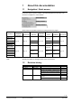
7 Revision numbers Product no. SAX31.00Y SAX31.03Y SAX61.03Y SAX81.00Y SAX81.03Y Valid from rev. no. ..E ..E ..E ..E ..E Product no. SAL31.00T10 SAL31.03T10 SAL61.00T10 SAL61.03T10 SAL81.00T10 SAL81.03T10 Valid from rev. no. ..A ..A ..A ..A ..A ..A 57 / 62 Siemens Building Technologies Electromotoric actuators SAX..Y, SAL..
8 Glossary 8.1 Symbols Caution, general danger – read the notes! Caution, hot surface – read the notes! Condition as supplied to costumer Crosstip screwdriver (Pozidriv) Slotted screwdriver Screw wrench Allen key 8.2 Terms DIL switches A DIL switch shows the switching choices in the form of a place value system (dual in line) in relation to basis 2 (on and off). DN Nominal size: Characteristic for matching parts of the piping system.
Index 3-position control .................................................. 35 A/D conversion ............................................... 35, 37 About this documentation ....................................... 5 Accessories .................................................... 13, 51 Electrical accessories........................................ 13 Mechanical accessories .................................... 13 Acting direction ............................................... 39, 41 Angular rotation ......
Modulating control ................................................ 37 Montagesatz ASK3..N ........................................... 12 Montagesatz ASK31N ........................................... 22 Motor control ................................................... 35, 37 Mounting ............................................................... 19 Accessories ....................................................... 24 Auxiliary switch ASC10.51.................................
/ 62 Siemens Building Technologies Electromotoric actuators SAX..Y, SAL..
Siemens Switzerland Ltd Building Technologies Group International Headquarters Gubelstrasse 22 CH-6301 Zug Phone +41 41-724 24 24 Fax +41 41-724 35 22 www.siemens.com/sbt © 2013 Siemens Switzerland Ltd Subject to change 62 / 62 Siemens Building Technologies Electromotoric actuators SAX..Y, SAL..