
User Manual
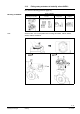
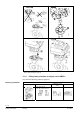
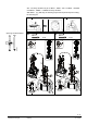
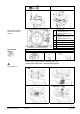
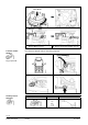
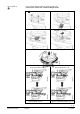
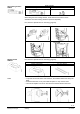
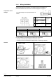
Table Of Contents
- 1 About this documentation
- 2 Engineering
- 3 Handling
- 4 Functions and control
- 4.1 3-position control
- 4.2 Modulating control
- 4.3 Function module AZX61.1
- 4.4 Positioning signal and flow characteristic selection
- 4.5 Acting direction and flow characteristic
- 4.6 Position Feedback U
- 4.7 Calibration
- 4.8 Signal priorities
- 4.9 Detection of valve seat
- 4.10 Detection of foreign bodies
- 4.11 Forced control Z
- 4.12 Technical and mechanical design
- 5 Technical data
- 6 Connection diagrams and dimensions
- 7 Revision numbers
- 8 Glossary
1
PZ 2
2
A
Plug-in space for…
• Potentiometer ASZ7.5/.., or
• Auxiliary switch ASC10.51
B
Plug-in space for…
• Function module AZX61.1 , or
• Auxiliary switch ASC10.51
C LED
D DIL switches
E Calibration slot
F Connection terminals
Interior view of setting
elements and plug-in
spaces
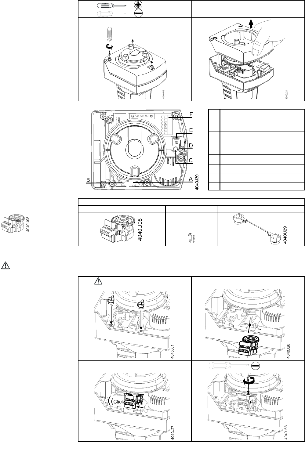
Scope of delivery
1 potentiometer ASZ7.5/.. 1 screw 2 screw covers
1 pc.
Potentiometer
ASZ7.5/..
• First, observe "Special notes on mounting" (page 24).
• Fit the sc
rew covers first – otherwise danger of life!
1
2
3
4
No.: 1
Plug-in sp
ace A
25 / 60
Siemens Actuators SAX.., SAL.. for valves CE1P4040en
Building Technologies Handling 22.12.2010