
User Manual
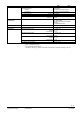
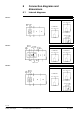
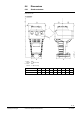
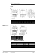
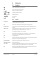
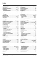
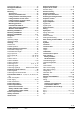

Table Of Contents
- 1 About this documentation
- 2 Engineering
- 3 Handling
- 4 Functions and control
- 4.1 3-position control
- 4.2 Modulating control
- 4.3 Function module AZX61.1
- 4.4 Positioning signal and flow characteristic selection
- 4.5 Acting direction and flow characteristic
- 4.6 Position Feedback U
- 4.7 Calibration
- 4.8 Signal priorities
- 4.9 Detection of valve seat
- 4.10 Detection of foreign bodies
- 4.11 Forced control Z
- 4.12 Technical and mechanical design
- 5 Technical data
- 6 Connection diagrams and dimensions
- 7 Revision numbers
- 8 Glossary
6.2 Connection terminals
6.2.1 Actuators
SA..31..
AC 230 V, 3-position
System neutral (SN)
Positioning signal (actuator’s stem extends / actuator’s spindle turns clockwise)
Positioning signal (actuator’s stem retracts / actuator’s spindle turns counter-clockwise)
SA..61..
AC/DC 24 V, DC 0…10 V / 4…20 mA / 0…1000
Sytem neutral (SN)
System potential (SP)
Positioning signal for DC 0…10 V / 4…20 mA
Measuring neutral
Position feedback DC 0...10 V
Positioning signal forced control AC/DC 24 V, 0...1000
SA..81..
AC/DC 24 V, 3-position
System potential (SP)
Positioning signal (actuator’s stem extends / actuator’s spindle turns clockwise)
Positioning signal (actuator’s stem retracts / actuator’s spindle turns counter-clockwise)
6.2.2 Electrical accessories
Auxiliar
y switch
ASC10.51
Adjustable switching points, AC 24…230 V
System potential (SP)
Closing (actuator’s stem extends / actuator’s spindle turns clockwise)
Opening (actuator’s stem extends / actuator’s spindle turns clockwise)
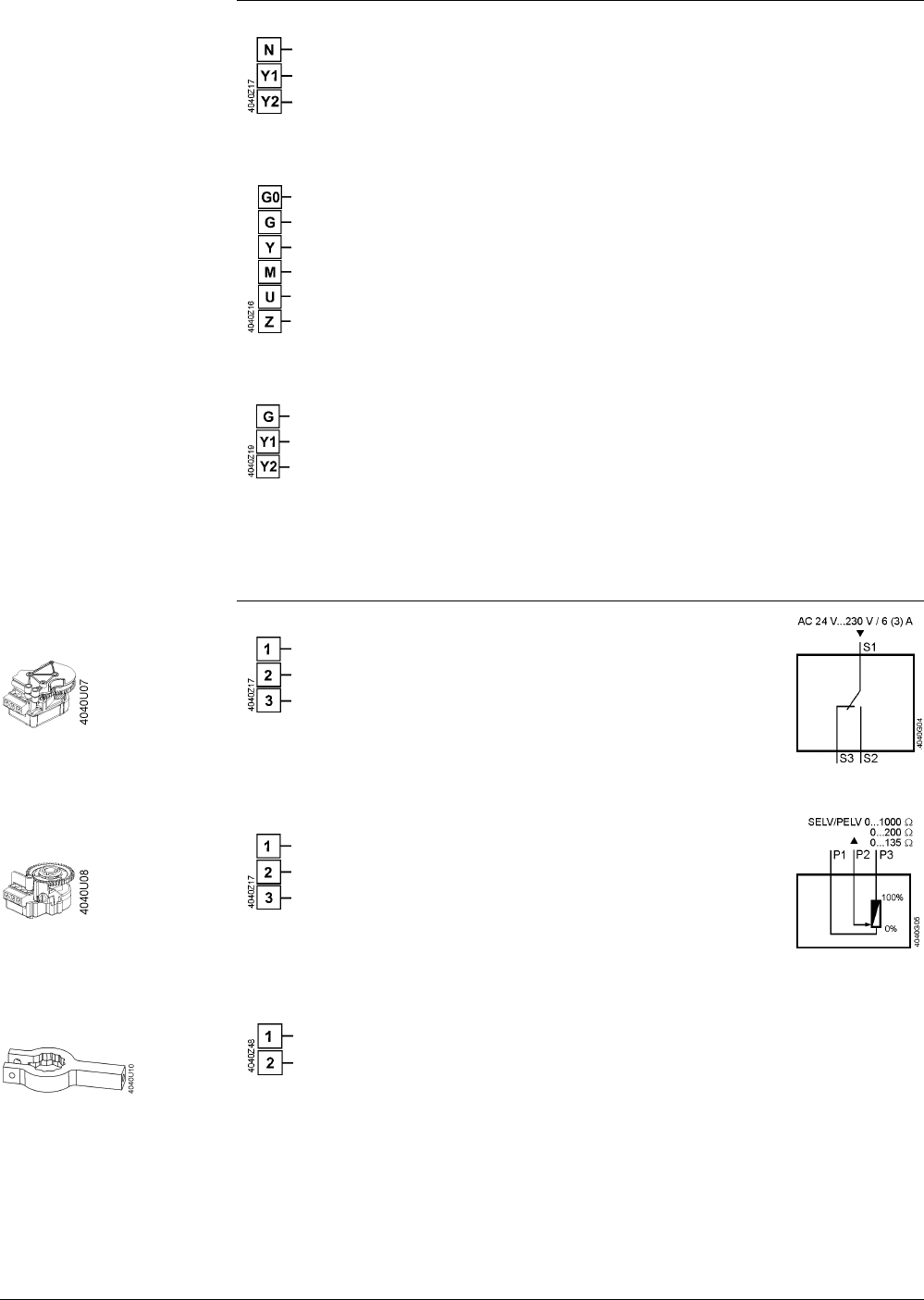
Adjustment of zero point, DC 10 V
Measuring neutral
0…x
x…0
x = 135 , 200 ;1000
Potentio
meter
ASZ7.5/..
Stem heating element
ASZ6.6
AC 24 V / 30 W
System neutral (SN) (red)
System potential (SP) (black)
53 / 60
Siemens Actuators SAX.., SAL.. for valves CE1P4040en
Building Technologies Connection diagrams and dimensions 22.12.2010