
User's Manual


Combination Starters & Starters for Group Installation
SIRIUS 3RA2 Motor Starters
General data
6/10
SIRIUS Innovations Supplement 2011
6
Order No. scheme
Note:
The Order No. scheme is presented here merely for information purposes and for better understanding of the logic behind the order
numbers.
For your orders, please use the order numbers quote in the catalog in the Selection and ordering data.
■
Technical specifications
Digit of the Order No. 1st -
3rd
4th 5th 6th 7th 8th 9th 10th 11th 12th 13th 14th 15th 16th
@@@ @ @ @ 0 – @ @ @ @ @ – @ @ @ @
SIRIUS starters 3 R A
SIRIUS 2nd generation 2
Type of starter (direct-on-line starter = 1,
reversing starter = 2)
@
Size (S00 = 1, S0 = 2) @
Setting range for overload release @ @
Design type and connection method @
Rated power at 460 V AC @ @
Integrated auxiliary switches of the contactor @
Operating range / solenoid coil circuit (contactor) @
Rated control supply voltage (contactor) @ @
Example
3 R A 2 1 1 0 – 0 B A 1 5 – 1 A K 6
Direct-on-line starters/
reversing starters
Size Connection methods Mounting Control voltage Width W Height H Depth D
mm mm mm
Mounting dimensions
Direct-on-line starters
3RA21.
S00
3RA21 1.
Screw terminals Standard mounting rails AC/DC 45 167 97
Busbar adapters AC/DC
45 200 155
Spring-type terminals Standard mounting rails AC/DC
45 198 97
Busbar adapters AC/DC
45 260 155
S0
3RA21 2.
Screw terminals Standard mounting rails AC
45 193 97
DC
45 193 107
Busbar adapters AC
45 260 155
DC
45 260 165
Spring-type terminals Standard mounting rails AC/DC
45 243 107
Busbar adapters AC/DC
45 260 165
Reversing starters
3RA22.
S00
3RA22 1.
Screw terminals Standard mounting rails AC/DC
90 170 97
Busbar adapters AC/DC
90 200 155
Spring-type terminals Standard mounting rails AC/DC
90 204 97
Busbar adapters AC/DC
90 260 155
S0
3RA22 2.
Screw terminals Standard mounting rail
adapters
AC
90 265 120.3
DC
90 265 130
Busbar adapters AC
90 260 155
DC
90 260 165
Spring-type terminals Standard mounting rail
adapters
AC/DC
90 270 131
Busbar adapters AC/DC
90 260 165
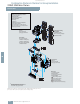
W
H
D
Type
3RA2. 1 3RA2. 2
Size
S00 S0
Number of poles
3 3
Mechanics and environment
Permissible ambient temperature
• During operation °C -20 ... +60
• Storage and transport °C
-55 ... +80
Weight kg 0.6 ... 1.5 0.8 ... 2.3
Permissible mounting
positions
Important: Acc. to DIN 43602 start command "I" at the right or top
Shock resistance
(sine-wave pulse)
Acc. to IEC 60086 Part 2-27
g
Up to 6 Up to 6
Degree of protection Acc. to IEC 60947-1
IP20
90°
90°
NSB00369
22,5°
22,5°
© Siemens AG 2011