
User Manual

4/11
Building Technologies Division CC1N7542en
21.06.2015
Mounting notes
Ensure that the relevant national safety regulations are complied with
Observe that the screw-on area must be flat.
Always use the AZL2… in dry and clean environments
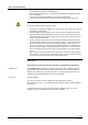
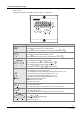
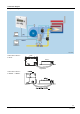
Step 1 Place the AZL2... into the cutout as
shown (without applying any force).
7542z01/0206
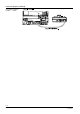
Step 2 Secure the AZL2… with the 2 Phillips-
head screws provided (without applying
any force).
7542z02/0206
Note:
If the AZL2... does not fit in the cutout,
check the dimensions of cutout and
housing.
Observe a tightening torque of 0.4 Nm for the screws to ensure the requirements of
IP54 are satisfied
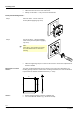
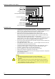
The units’ mounting dimensions are 92 x 92 mm. Due to the front’s dimensions, the
resulting spacing is 96 mm. Thanks to the mounting mechanism, the units can be fitted
in panel fronts of different material thicknesses (1...3 mm).
96
1...3
92
+0.8
-0
92
+0.8
-0
7542m02/0306
96
Ensure that the mounting surface is completely flat
Use screws M5 with washers (e.g. similar to 10-UNF)
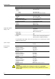
Flush-panel mounting AZL23…
Dimensions of cutout
AZL23…
AZL21…