Siemens BACnet ATEC Owner's Manual Siemens Industry, Inc. 125-5050, Rev.
Technical specifications and availability subject to change without notice. © 2010 Copyright Siemens Industry, Inc. We reserve all rights in this document and in the subject thereof. By acceptance of the document the recipient acknowledges these rights and undertakes not to publish the document nor the subject thereof in full or in part, nor to make them available to any third party without our prior express written authorization, nor to use it for any purpose other than for which it was delivered to him.
Copyright Notice Copyright Notice Notice Document information is subject to change without notice by Siemens Industry, Inc. Companies, names, and various data used in examples are fictitious unless otherwise noted. No part of this document may be reproduced or transmitted in any form or by any means, electronic or mechanical, for any purpose, without the express written permission of Siemens Industry, Inc. Warning This equipment generates, uses, and can radiate radio frequency energy.
Copyright Notice radio communications. However, there is no guarantee that interference will not occur in a particular installation. If this equipment does cause harmful interference to radio or television reception, which can be determined by turning the equipment off and on, the user is encouraged to try to correct the interference by one or more of the following measures: Reorient or relocate the receiving antenna. Increase the separation between the equipment and receiver.
Table of contents Copyright Notice .......................................................................................3 How To Use This Manual .......................................................................... 7 Chapter 1 – Product Overview ................................................................. 9 Hardware Inputs ...................................................................................................... 10 Hardware Outputs ....................................................
Using the Controller as a Point Extension Device ..............................................22 Chapter 3 – Point Database ................................................................... 24 Chaper 4 – Troubleshooting .................................................................. 30 Basic Service Information ........................................................................................ 30 Preventive Maintenance .............................................................................
How To Use This Manual How To Use This Manual This manual is written for the owner and user of the Siemens Industry BACnet VAV Actuator. It is designed to help you become familiar with the Siemens BACnet VAV Actuator and its applications. This section covers manual organization, manual conventions, symbols used in the manual, and other information that will help you use this manual.
How To Use This Manual Convention Examples dialog box. Error and system messages are displayed in Courier New font. The message Report Definition successfully renamed displays in the status bar. New terms appearing for the first time are italicized. The PXC Modular continuously executes a user-defined set of instructions called the control program. This symbol signifies Notes. Notes provide additional information or helpful hints.
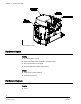
Chapter 1 – Product Overview Chapter 1 – Product Overview The BACnet Actuating Terminal Equipment Controller (ATEC) is the Siemens Industry FLN controller used in pressure independent Variable Air Volume applications (See the following figure.). It provides Direct Digital Control (DDC) for eight applications, and can operate independently as a stand-alone DDC room controller or networked with a field panel. The controller provides all input/output, system, and local communication connections.
Chapter 1 – Product Overview Siemens BACnet ATEC Hardware Inputs Analog Air Velocity Sensor (AVS) Duct temperature sensor (optional) – Application 2861 Room temperature sensor (RTS) Room temperature setpoint dial (optional) Digital Night mode override (optional) Wall switch (optional) Hardware Outputs Analog None 10 Siemens Industry, Inc. 125-5050, Rev.
Chapter 1 – Product Overview Digital Application Damper Actuator All Fan 2865, 2866, 2867 First valve actuator (required) 2863 Stage 1 electric reheat; or, 2-position heating valve 2862 Stage 1 electric reheat 2864, 2866 Stage 2 electric reheat (optional) 2862, 2864, 2866 Stage 3 electric reheat (optional) 2862 Valve actuator 2865, 2867 Power Wiring The controller is powered by 24 Vac.
Chapter 1 – Product Overview Communication Wiring The controller connects to the field panel by means of a Floor Level Network (FLN) trunk. Communication wiring connects to the three screw terminals on the controller labeled “+” (positive), “-“(negative), and “S” (Shield). See the following figure. Controller LED Indicators The controller has six Light Emitting Diode (LED) indicators (see the figure Siemens BACnet ATEC). Controller LEDs.
Chapter 1 – Product Overview Temperature Sensors Room Temperature Sensor The controller room temperature sensor connects to the controller by means of a cable terminated at both ends with a six-conductor RJ-11 plug-in connector. Duct Temperature Sensor An optional duct temperature sensor provides duct air temperature sensing inputs to the controller. For more information about temperature sensors, contact your local Siemens Industry representative.
Chapter 2 – Applications Chapter 2 – Applications Basic Operation The BACnet ATEC provides Direct Digital Control (DDC) for Variable Air Volume (VAV) terminal box applications. Temperature control varies with the application. If present, heating can be provided by hot water, up to three stages of electric reheat, or optional baseboard radiation. Sequencing Logic (optional) This application has the additional capability to sequence the flow and mechanical heating when heated supply air is available.
Chapter 2 – Applications Calibration Air Velocity Sensor Calibration of the controller's internal air velocity sensor is periodically required to maintain accurate air velocity readings. Calibration may be set to take place automatically or manually. Autozero Module (AZM) Used when damper cannot be closed and constant airflow is needed. For a controller used with an AZM, calibration occurs without closing the damper. Application 6520, 6521, 6522, 6523.
Chapter 2 – Applications Modulate Damper During Heating Mode (optional) CAUTION If the damper is set to modulate in heating mode, make sure the controller is in the appropriate mode for the current supply air temperature. Applications that have a heating source (valve/electric) can be configured to modulate the flow setpoint in sequence with the heating source. Hot Water Reheat CAUTION Do not set HTG FLOW MIN to 0 cfm (0 lps).
Chapter 2 – Applications 3. “Safeties by Others”: This note implies that the associated equipment has safety features installed, for example adding mechanical stops to the dampers. Application 2860 VAV Cooling Only In Application 2860, the controller modulates the supply air damper of the terminal box for cooling. In order for it to work properly, the central air-handling unit must provide cool supply air. See the following figure.
Chapter 2 – Applications Baseboard Radiation Baseboard radiation can be a two-position valve or electrical resistance heating. If the controller is in cooling mode, the heating valve is closed. When in heating mode, the controller will operate the heating valve to maintain the heating setpoint. Electric Heat Interlock CAUTION Do not set EHEAT FLOW (the defined minimum) to less than 5%; otherwise, the electric heat interlock will be disabled.
Chapter 2 – Applications Application 2864 VAV Series Fan Powered with Electric Reheat In Application 2864, the controller modulates the supply air damper of the terminal box for cooling and controls stages of electric reheat for heating. When in heating, the terminal box either maintains minimum airflow or modulates the supply air damper. Application 2864 has a series fan for air circulation. In order for the terminal box to work properly, the central air-handling unit must provide supply air.
Chapter 2 – Applications [insert TEC2564CD] Application 2865 VAV Series Fan Powered with Hot Water Reheat In Application 2865, the controller modulates the supply air damper of the terminal box for cooling and modulates a hot water valve for heating. When in heating, the terminal box either maintains minimum airflow or modulates the supply air damper. Application 2865 has a series fan for air circulation.
Chapter 2 – Applications See the following figure. Fan Operation The fan turns on when heating is required. [insert TEC2566CD] Application 2867 VAV Parallel Fan Powered with Hot Water Reheat In Application 2867, the controller modulates the supply air damper of the terminal box for cooling and modulates a hot water valve for heating. When in heating, the terminal box either maintains minimum airflow or modulates the supply air damper. Application 2867 has a parallel fan that re-circulates the room air.
Chapter 2 – Applications Fan Operation The fan turns on when heating is required. [insert TEC2567CD] Application 2897 Slave Mode Application 2897 is the slave mode application for the BACnet ATEC (see Ordering Notes [ 9] for product numbers). Slave mode is the default application that comes up when power is first applied to the controller. Slave mode provides no control.
Chapter 2 – Applications DO 3, DO 4, and DO 5 may be used as separate DOs or in pairs to control a motor as shown in the example. NOTE: If using either a motor or DOs as auxiliary points, be sure to set MTR SETUP to the correct value. If using a pair of DOs to control a motor, then the DOs cannot be unbundled. Only MTR COMD can be unbundled to control the motors. Contact your local Siemens Industry representative for other combinations of DOs and motors. 23 Siemens Industry, Inc. 125-5050, Rev.
Chapter 3 – Point Database Chapter 3 – Point Database Chapter 3 presents a description of the BACnet VAV Controller — Electronic Output point database, including point descriptors, point addresses, and a listing of applications in which each point is found. Descriptor Address1 Application CTLR ADDRESS 01 All Identifies the controller on the FLN trunk. APPLICATION 02 All Identification number of the program running in the controller.
Chapter 3 – Point Database Descriptor Address1 Application FLOW START 16 All except 2560, 2561, 2597 Determines how the damper modulation will be sequenced while in heating mode. When HTG LOOPOUT is above this value, then FLOW STPT starts to increase. FLOW END 17 All except 2560, 2561, 2597 Determines how the damper modulation will be sequenced while in heating mode. When HTG LOOPOUT is below this value, then FLOW STPT starts to decrease.
Chapter 3 – Point Database Descriptor Address1 Application Description the space in cooling mode. CLG FLOW MAX 32 All except 2597 The maximum amount of air in CFM (LPS) to be supplied to the space in cooling mode. HTG FLOW MIN 33 All except 2560, 2597 The minimum amount of air in CFM (LPS) to be supplied to the space in heating mode. HTG FLOW MAX 34 All except 2560, 2597 The maximum amount of air in CFM (LPS) to be supplied to the space in heating mode.
Chapter 3 – Point Database Descriptor Address1 Application Description travel (for use as an auxiliary slave point). This value is calculated based on motor run time. See MTR2 TIMING. VLV POS {53} 2565 The current position of the valve in percent of full travel for applications using a water valve. This value is calculated based on motor run time. VLV1 POS {53} 2563 The current position of valve 1 in percent of full travel for applications using a water valve.
Chapter 3 – Point Database Descriptor Address1 Application FLOW {75}2 Description All except 2597 Indicates the amount of air currently passing the air velocity sensor. The value is calculated as a percentage based on where the value of AIR VOLUME is in the range between 0 and CTL FLOW MAX. CTL FLOW MIN {76}2 All except 2597 The active minimum flow used as a limit for the flow control loop.
Chapter 3 – Point Database Descriptor Address1 Application 90 All except 2560, 2561, 2597 CTL STPT {92} All except 2597 The actual setpoint value being used as input for the active temperature control loop. FLOW STPT {93} All except 2597 The setpoint of the flow control loop. CAL AIR {94} All YES commands the controller to go through calibration sequence for the air velocity transducers. YES is also displayed when the calibration sequence is started automatically.
Chaper 4 – Troubleshooting Chaper 4 – Troubleshooting This chapter describes corrective measures you can take should you encounter a problem when using a BACnet ATEC. You are not required to do any controller troubleshooting. You may want to contact your local Siemens Industry representative if a problem occurs or you have any questions about the controller. NOTE: When troubleshooting, record what the problem is and what actions were performed immediately before the problem occurred.
Chaper 4 – Troubleshooting Safety Features The controller board stores the controller's address, applications, and point values. In the event of a power failure or a reset, these values are retrieved from the controller's permanent memory and are used by the controller unless overridden by a field panel. If one of the following conditions occurs, the controller will activate safety features present in its fail-safe mode. Sensor failure. Loss of power.
Glossary Glossary The glossary contains terms and acronyms that are used in this manual. For definitions of point database descriptors, see Chapter 3 - Point Database [ 24] , in this manual. airflow Rate at which a volume of air moves through a duct. Usually expressed in cubic feet per minute (cfm) or liters per second (lps). algorithm Mathematical formula that uses varying inputs to calculate an output value. AVS Air Velocity Sensor.
Glossary field panel A device containing a microprocessor for centralized control of system components and equipment controllers. FLN Field Level Network. Network consisting of equipment controllers, FLN end devices, fume hoods, etc. lps Liters per Second. loopout Output of the control loop expressed as a percentage. HMI Human Machine Interface. Terminal and its interface program that allows you to communicate with a field panel or equipment controller.
Glossary slave mode Default application that displays when power is first applied to an equipment controller. No control action is initiated in the slave mode. stand-alone control Type of control offered by a controller that is providing independent DDC control to a space. Terminal Equipment Controller Siemens Industry, Inc.
Index Index A control drawing, 20 Air Velocity Sensor (AVS), 12 overview, 20 algorithm, 33 application 2562 baseboard radiation, 11 application 2564 control drawing, 21 Application 2564 fan operation, 21 application 2566 control drawing, 23 fan operation, 23 application 2567 control drawing, 24 Application 2567 fan operation, 24 Application 2597 using auxiliary points, 24 application 2860 control drawing, 19 overview, 19 application 2861 control drawing, 19 overview, 19 application 2862 baseb
Index B loopout, 34 Basic Sanity Test (BST), 32 O basic service information, 31 override switch, 34 BST LED, 32 P C PID, 34 centralized control, 33 point database overview, 25 communication wiring, 14 control loop, 33 power wiring, 13 controller preventive maintenance, 31 LEDs/LED indicators, 32 R D related equipment, 15 DDC, 33 relay module, 15 Direct Digital Control (DDC), 11, 16 RTS, 34 DO, 33 RX LED, 32 E S English units, 33 safety features, 32 equipment controller, 33, 35
Index W communication wiring, 14 wiring power wiring, 13 37 Siemens Industry, Inc. 125-5050, Rev.
Issued by Siemens Industry, Inc. Building Technologies Division 1000 Deerfield Parkway Buffalo Grove, IL 60089, USA Tel. +1 847-215-1000 Document ID 125-5050, Rev. AA Edition 4/20/2010 © 2010 Copyright Siemens Industry, Inc. Technical specifications and availability subject to change without notice.