
Specifications


Siemens Mobility, Traffic Solutions
Sopers Lane, Poole, Dorset
BH17 7ER
Version 10 Page 116 of 120 Status Issued
Last Editor harry.smyth Date 03 November 2014
Document
Name
GENERAL HANDBOOK FOR HEIMDALL
DETECTORS
Doc. No.
667/HB/31900/000
Copyright Siemens plc 2014 All Rights Reserved
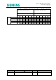
For the Siemens supplied ELV detector power extension kit the following table can be
consulted.
Kit
160VA ELV Supply
667/1/33074/000
50VA ELV Supply
667/1/33075/000
Transformer Part Number 667/7/15855/024 667/7/00977/024
Resistance Rs 0.309 ohms 1.3 ohms
Worst case no-load
voltage at 207 volts
mains (i.e. 230v -10%)
Vmin 21.26v 23.13v
Maximum current Imax 6.6 A 2 A
Table 12-2 – Siemens AC Detector Supply Specification
12.2 Method Outline
The voltage falls by Rs in (e.g. in Table 12-1) for each amp of current drawn from the
transformer. For each individual cable there is a voltage drop down the cable of 0.042
volts for each go-and-return metre of (1 mm
2
) cable. Therefore the current must be
calculated for each cable run using the current per detector shown in , Section 3, for each
detector (I
s
). The total current must then be calculated for all detectors supplied from the
transformer. The maximum length of cable can be then calculated.
12.3 Calculating Cable Lengths
12.3.1 24V DC Supply Feed
When the Heimdall Detector is powered from the associated controller’s 24V DC supply
first calculate the total detector supply load. This must not exceed the limits of that
available for this particular installation.
Check that the minimum supply voltage at this load is greater than the detector minimum
voltage of 19.2V.
For each detector supply cable calculate:
Maximum cable length = __Vs (min) - 19.2 _
total cable current x 0.042
Where: Vs = 24V PSU output voltage negative tolerance.
0.042 = cable resistance in ohms per metre.
If longer cables are required, the arrangements must be revised. For example by using
two cable cores in parallel the maximum cable length changes to:
_ Vs (min) - 19.2 _
total cable current x 0.021