Siemens BT300 HVAC Drive Installation Instructions DPD01148 2019-05-29 Smart Infrastructure DPD01148, Rev.
Copyright Notice Copyright Notice Notice Document information is subject to change without notice by Siemens Industry, Inc. Companies, names, and various data used in examples are fictitious unless otherwise noted. No part of this document may be reproduced or transmitted in any form or by any means, electronic or mechanical, for any purpose, without the express written permission of Siemens Industry, Inc.
Table of contents Chapter 1 - Safety ......................................................................................................... 5 Dangers ...................................................................................................................................... 6 Warnings .................................................................................................................................... 9 Notices.......................................................................
Option Board Installation ..................................................................................................... 61 Battery Installation for Real Time Clock (RTC) ............................................................... 62 Galvanic Isolation Barriers ................................................................................................... 62 Chapter 6 - Commissioning .......................................................................................
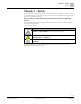
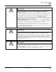
Chapter 1 - Safety Dangers Chapter 1 - Safety This manual contains clearly marked Caution, Warning, and Danger notices, which are intended for your personal safety and to avoid any unintentional damage to the product or connected devices. Please carefully read the information included in the Caution and Warning notices. The following table lists the safety symbols used in this manual to draw attention to important information. Table 1: Warning Symbols.
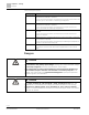
Chapter 1 - Safety Dangers Table 2: Warning Descriptions. Warning Type DANGER Description Serious injury, death, or severe equipment damage is imminent if a procedure or instruction is not followed as specified. Le non respect d'une procédure ou instruction peut provoquer instantanément des blessures graves, voir mortelles, ou endommager l'équipement WARNING Serious injury, death, or severe equipment damage could occur if a procedure or instruction is not followed as specified.
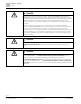
Chapter 1 - Safety Dangers DANGER Always ensure absence of voltage before starting any electrical work! After disconnecting the drive from line voltage, wait until the indicators on the keypad go out (if no keypad is attached see the indicators on the cover). Wait 5 more minutes before doing any work on the connections of the BT300 Drive. Do not open the cover before this time has expired. After expiration of this time, use a measuring equipment to absolutely ensure that no voltage is present.
Chapter 1 - Safety Dangers DANGER During a ramp stop (coast stop) (see the Siemens BT300 Operator's Manual (DPD01809), the motor is still generating voltage to the drive. Therefore, do not touch the components of the drive before the motor has completely stopped. Wait until the indicators on the keypad go out. (If no keypad is attached see the indicators on the cover.) Wait an additional 5 minutes before starting any work on the drive.
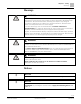
Chapter 1 - Safety Warnings Warnings WARNING At power-up, power brake, or fault reset, the motor will start immediately if the start signal is active unless pulse control has been selected for Start/Stop logic. Furthermore, the I/O functionalities (including start inputs) may change if parameters, applications or software are changed. Therefore, disconnect the motor if an unexpected start can cause danger.
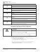
Chapter 1 - Safety Grounding and Ground Fault Protection NOTICE Only spare parts delivered by Siemens Industry, Inc. can be used. NOTICE Do not touch the components on the circuit boards. Static voltage discharge may damage the components. NOTICE Check that the EMC level of the drive corresponds to the requirements of your supply network. See the Installation in an IT System [➙ 67] section. NOTICE In a domestic environment, this product may cause radio interference.
Chapter 1 - Safety Grounding and Ground Fault Protection • or Provision of an additional terminal for a second protective grounding conductor of the same cross-sectional area as the original protective grounding conductor. Table 3: Protective Grounding Conductor Cross-Section.
ogies Product Numbers 2017-09eading 1_noNr" \* MERGEFORMAT Chapter 2 - Receipt of Delivery Chapter 2 - Receipt of Delivery Check the accuracy of the delivery by comparing your order data to the drive information found on the package label. If the delivery does not correspond to your order, contact the supplier immediately. Product Numbers Siemens product numbers consist of 15 characters and one optional character for factory-installed options.
Chapter 2 - Receipt of Delivery Unpacking and Lifting the Drive Unpacking and Lifting the Drive The weights of the drives vary greatly according to the size. You may need to use special lifting equipment to remove the drive from its package. Note the weights of each individual frame size in the table below. Table 4: Frame Weights. Frame Weight in kgs (lbs) FS4 6.0 (13.2) FS5 10.0 (22) FS6 20.0 (44.1) FS7 37.5 (82.7) FS8 66.0 (145.5) FS9 108.0 (238.
ogies Accessories 2017-09eading 1_noNr" \* MERGEFORMAT Chapter 2 - Receipt of Delivery Max. 45° 9012.emf Figure 1: Lifting Bigger Frames. Siemens BT300 HVAC Drives have undergone scrupulous tests and quality checks at the factory before they are delivered to the customer. However, before and after unpacking the product, check for any product damage that may have occurred during shipment and that and that the delivery is complete.
Chapter 2 - Receipt of Delivery Accessories NOTE: The accessories bag is located under the drive cover. Size FS4 Table 5: Contents of Accessories Bag, FS4.
ogies Accessories 2017-09eading 1_noNr" \* MERGEFORMAT Chapter 2 - Receipt of Delivery Size FS6 Table 7: Contents of Accessories Bag, FS6.
Chapter 2 - Receipt of Delivery Accessories Size FS8 Table 9: Contents of Accessories Bag, FS8. Item Quantity Purpose M4 × 16 screw 3 Screws for control cable clamps Control cable grounding lamella 3 Control cable grounding Cable lugs KP40 3 Clamping power cables Cable insulator 11 Avoiding contact between cables Cable grommet, hole diameter 0.99 in. (25.
Chapter 3 - Mounting Dimensions in Millimeters (Inches) Chapter 3 - Mounting The drive must be mounted in the vertical position on the wall or on the back plane of an enclosure. Ensure that the flatness variation does not exceed 0.12 in (3 mm). If the conditions of the mounting place require horizontal mounting, the functionalities within the given nominal values stated in Chapter 7 - Technical data [➙ 77] cannot be guaranteed.
Chapter 3 - Mounting Dimensions in Millimeters (Inches) Figure 3: Siemens BT300 HVAC Drive Dimensions, FS5, Wall Mount. Siemens Industry, Inc.
Chapter 3 - Mounting Dimensions in Millimeters (Inches) Figure 4: Siemens BT300 HVAC Drive Dimensions, FS6, Wall Mount. 20 | 82 Siemens Industry, Inc.
Chapter 3 - Mounting Dimensions in Millimeters (Inches) Figure 5: Siemens BT300 HVAC Drive Dimensions, FS7, Wall Mount. Siemens Industry, Inc.
Chapter 3 - Mounting Dimensions in Millimeters (Inches) Figure 6: Siemens BT300 HVAC Drive Overall Dimensions, FS8 Type 1/IP21 and Type 12/IP54. 22 | 82 Siemens Industry, Inc.
Chapter 3 - Mounting Dimensions in Millimeters (Inches) Figure 7: Siemens BT300 HVAC Drive Detailed Dimensions, FS8 Type 1/IP21 and Type 12/IP54. Siemens Industry, Inc.
Chapter 3 - Mounting Dimensions in Millimeters (Inches) Figure 8: Siemens BT300 HVAC Drive Overall Dimensions, FS9 Type 1/IP21 and Type 12/IP54. 24 | 82 Siemens Industry, Inc.
Chapter 3 - Mounting Dimensions in Millimeters (Inches) Figure 9: Siemens BT300 HVAC Drive Detailed Dimensions, FS9 Type 1/IP21 and Type 12/IP54. Siemens Industry, Inc.
Chapter 3 - Mounting Cooling Flange Mount The drive can also be recessed into the cabinet wall or similar surface. A special flange mount option is available for this purpose. For further information see the Siemens BT300 Flange Mount Kits for Frames FS4 to FS7 Mounting Instructions (DPD01156). Cooling The drive produces heat when operating and is cooled down with air circulated by a fan. Ensure that enough free space is left around the drive for air circulation and cooling.
Chapter 3 - Mounting Cooling Table 11: Minimum Clearances Around the Drive. Minimum Clearance in Inches (mm). Type A1 B1 C D FS4 0.78 (20 ) 0.78 (20 ) 3.93 (100) 1.96 (50) FS5 0.78 (20 ) 0.78 (20 ) 4.72 (120) 2.36 (60) FS6 0.78 (20 ) 0.78 (20 ) 6.29 (160) 3.14 (80) FS7 0.78 (20 ) 0.78 (20 ) 9.84 (250) 3.93 (100) FS8 0.78 (20 ) 0.78 (20 ) 11.8 (300) 5.90 (150) FS9 0.78 (20 ) 0.78 (20 ) 13.8 (350) 7.
Chapter 3 - Mounting Cooling C+D FRONT 9014.emf SIDE Figure 11: Installation Space When Drives are Mounted Above Each Other. 28 | 82 Siemens Industry, Inc.
Chapter 4 - Power Cabling Cooling Chapter 4 - Power Cabling The line voltage cables are connected to terminals L1, L2 and L3 and the motor cables to terminals marked with U, V and W. See the following figure. See Table Cable Types Required to Meet Standards for the cable recommendations for different EMC levels. Figure 12: Connection Diagram. Use cables with heat resistance of at least +70°C (158°F).
Chapter 4 - Power Cabling UL Criteria for Cabling and Fusing PE conductor and shield PE conductors Shield 9007.emf Figure 13: Conductor Cross-sections. NOTES: The factory-default switching frequencies (all frames) meet EMC requirements. If the safety switch is connected, the EMC protection is continuous over the entire cable installation.
Chapter 4 - Power Cabling UL Criteria for Cabling and Fusing Table 14: Cable and Fuse Sizes for Siemens BT300 (FS4 to FS9). IL [A] Fuse (Class J/T) [A] Line, Motor and Ground Cable Cu BT300-001X2… 4.2 6 BT300-00152… 6.0 BT300-002X2… Frame FS4 FS5 FS6 Type Terminal Cable Size Main Ground AWG14 AWG24 - AWG10 AWG17 - AWG10 6 AWG14 AWG24 - AWG10 AWG17 - AWG10 7.2 10 AWG14 AWG24 - AWG10 AWG17 - AWG10 BT300-003X2… 9.7 15 AWG14 AWG24 - AWG10 AWG17 - AWG10 BT300-00154… 3.
Chapter 4 - Power Cabling Cable Installation IL [A] Fuse (Class J/T) [A] Line, Motor and Ground Cable Cu BT300-025X2… 69.0 100 BT300-030X2… 82.1 BT300-040X2… Frame FS7 FS8 FS9 Type Terminal Cable Size Main Main AWG2 AWG9 - AWG2/0 AWG9 - AWG2/0 110 AWG1 AWG9 - AWG2/0 AWG9 - AWG2/0 99.0 150 AWG1/0 AWG9 - AWG2/0 AWG9 - AWG2/0 BT300-050X4… 67.5 100 AWG2 AWG9 - AWG2/0 AWG9 - AWG2/0 BT300-060X4… 85.3 110 AWG1 AWG9 - AWG2/0 AWG9 - AWG2/0 BT300-075X4… 100.
Chapter 4 - Power Cabling Cable Installation • • Avoid placing the motor cables in long parallel lines with other cables. If the motor cables run in parallel with other cables note the minimum distances between the motor cables and other cables given in the following table. Distance Between Cables, m (ft) Shielded Cable, m (ft) 1.0 (0.3) ≤ 164 (50) 3.2 (1.0) ≥ 656 (200) • The given distances also apply between the motor cables and signal cables of other systems.
Chapter 4 - Power Cabling Cable Installation 2. Open the drive cover. Figure 15: Opening Cover. 3. Remove the screws of the cable protection plate. Do not open the cover of the power unit. Figure 16: Removing screws 34 | 82 Siemens Industry, Inc.
Chapter 4 - Power Cabling Cable Installation 4. Insert the cable grommets (included in the delivery) in the openings of the cable entry plate (included). 5. • • • Insert the cables - supply cable and motor cable - in the openings of the cable entry plate. Then cut the rubber grommets open to slide the cables through. Should the grommets fold in while inserting the cable, just draw the cable back a bit to straighten the grommets up.
Chapter 4 - Power Cabling Cable Installation R+ R- U V W 9232.emf Figure 18: Cable Entry Plate and Cables. 7. Connect the stripped cables (see Figure 18 [➙ 33] and Table [➙ 33]17) as shown in Figure 25 [➙ 33]. • Expose the shield of all three cables in order to make a 360-degree connection with the cable clamp (1). • Connect the (phase) conductors of the supply and motor cables into their respective terminals (2).
Chapter 4 - Power Cabling Cable Installation Tightening Torques of Cable Terminals: Table 16: Tightening Torques of Terminals. Maximum Tightening Torque Nm/lb-in. Frame Product Number Power and Motor Terminals Nm FS4 BT300-001X2… 0.6 EMC Grounding Clamps lb-in. 5.3 Nm 1.5 Grounding Terminals lb-in. 13.3 Nm 2.0 lb-in. 17.7 BT300-00152… BT300-002X2… BT300-003X2… BT300-00154… BT300-002X4… BT300-003X4… BT300-005X4… BT300-00754… Siemens Industry, Inc.
Chapter 4 - Power Cabling Cable Installation Maximum Tightening Torque Nm/lb-in. Frame Product Number Power and Motor Terminals Nm FS5 BT300-005X2… EMC Grounding Clamps lb-in. Nm Grounding Terminals lb-in. Nm lb-in. 1.5 13.3 1.5 13.3 2.0 17.7 10 88.5 1.5 13.3 2.0 17.7 Torx - 8.0 Hex - 5.6 Torx - 70.8 Hex - 49.6 1.5 13.3 Torx - 8.0 Hex - 5.6 Torx - 70.8 Hex - 49.
Chapter 4 - Power Cabling Cable Installation 9233.emf = M5; 2 Nm Figure 20: Additional Protective Grounding Connector. 9. Re-mount the cable protection plate (Figure 27 [➙ 33]) and the cover of the drive. Figure 21: Re-mounting the Cover Components. Siemens Industry, Inc.
Chapter 4 - Power Cabling Cable Installation Frames FS8 and FS9 1. Strip the motor and line voltage (mains) cables as outlined in the following figure and table. Earth conductor Earth conductor A1 C1 C2 B1 D1 D2 MAINS MOTOR 9019.emf E Figure 22: Stripping the Cables. Table 17: Cable Stripping Lengths in Inches (mm). A1 B1 C1 D1 C2 D2 E FS8 Frame 1.57 (40) 7.08 (180) 0.98 (25) 11.8 (300) 0.98 (25) 11.8 (300) FS9 1.57 (40) 7.08 (180) 0.98 (25) 11.8 (300) 0.98 (25) 11.
Chapter 4 - Power Cabling Cable Installation 3. Remove the cable cover (1) and the cable fitting plate (2). M4x8 1 9029.emf M4 x 8 2 9039.emf Figure 24: Removing the Cable Cover and Cable Fitting Plate (FS8). Siemens Industry, Inc.
Chapter 4 - Power Cabling Cable Installation M4 x 8 M5 x 10 2 1 9041.emf Figure 25: Removing the Cable Cover and Cable Fitting Plate (FS9). 4. FS9 only: Loosen the screws and remove the sealing plate. FS9 M4x8 9048bt Figure 26: Removing the Sealing Plate (FS9). 5. Remove the EMC shield plate. M4x8 Wing nut M5 BT9026 Figure 27: Removing EMC Shield Plate; Left: FS8, Right: FS9. 42 | 82 Siemens Industry, Inc.
Chapter 4 - Power Cabling Cable Installation 6. Locate the terminals. Figure 28: Power Terminals: Left: FS8, Right FS9. 9040.emf Figure 29: Placing the Grommet. Siemens Industry, Inc.
Chapter 4 - Power Cabling Cable Installation 7. If you use thick cables, insert the cable insulators in between the terminals to avoid contact between the cables. Figure 30: Inserting the Cable Insulators. 8. Connect the stripped cables as shown in the following figure. a. Connect the (phase) conductors of the supply and motor cables into their respective terminals. b.
Chapter 4 - Power Cabling Cable Installation L1 L2 L3 DC+ DC- R+ R- L1 L2 L3 R+ DC- DC+ R- U V W U V W a a a b b b 9025.emf Figure 31: Connecting Power Cables; Left: FS8, Right: FS9. Connector Cable lug Cable lug 9015.emf Figure 32: Placing Two Cable Lugs on Top of Each Other. Siemens Industry, Inc.
Chapter 4 - Power Cabling Cable Installation Tightening Torques of Cable Terminals: Table 18: Tightening Torques of Terminals. Maximum Tightening Torque Nm/lb-in. Frame FS8 Product Number BT300-050X2… Power and Motor Terminals EMC Grounding Clamps Grounding Terminals Nm lb-in. Nm lb-in. Nm lb-in. 30 266 1.5 13.3 20 177 40 354 1.5 13.
Chapter 4 - Power Cabling Cable Installation 9035.emf Figure 33: Exposing Cable Shields. 10. First, remount the EMC shield plate (see Figure 33 [➙ 40]), and then remount the FS9 sealing plate (see Figure 32 [➙ 40]). 11. Reattach the cable fitting plate and then the cable cover. Figure 34: Reattaching Cable Fitting Plate and Cover. 12. FS9 only: Re-mount the main cover (unless you want to make the control connections first). Siemens Industry, Inc.
Chapter 4 - Power Cabling Cable Installation Figure 35: Re-mounting the Main Cover (FS9). 13. Check the connection of the grounding cable to the motor and the drive terminals marked with . NOTICE Two protective conductors are required according to standard EN 61800-5-1. For more information, see the Grounding and ground fault protection section [➙ 10].
Chapter 4 - Power Cabling Installation in Corner-Grounded Network Figure 36: Connecting the Protective Conductor. Installation in Corner-Grounded Network Corner grounding is allowed for the drive types FS7 to FS9 with a rating from 72A to 310A at 380 to 480V supply and from 75A to 310A at 208 to 240V supply. In these circumstances the EMC protection class must be changed to level C4 following the instructions in Chapter 6, Installation in an IT System section of this manual.
Chapter 5 - Control Unit Installation in Corner-Grounded Network Chapter 5 - Control Unit The control unit of the AC drive consists of the control board and additional boards (option boards) connected to the slot connectors of the control board. Figure 37: Location of Control Unit Components.
Chapter 5 - Control Unit Control Cable Sizing measurements of the main circuit (for example, DC-link voltage, unit temperature) are not available when line voltage is not connected. Control Cable Sizing The control cables shall be at least 0.5 mm2 (30 AWG) screened multi-core cables, see the table in the Power Cabling section. The maximum terminal wire size is 2.5 mm2 (14 AWG) for the relay and other terminals. The following table outlines the tightening torques of the control and relay board terminals.
Chapter 5 - Control Unit Control Terminals and DIP Switches Figure 38: Control I/O Terminal Signals on Basic I/O Board and Connection Example. *Digital inputs can be isolated from ground, see the Selecting Terminal Functions and Isolating Digital Inputs from Ground with DIP Switches section. Figure 39: Slot B Terminal Connections. 52 | 82 Siemens Industry, Inc.
Chapter 5 - Control Unit Control Terminals and DIP Switches Selecting Terminal Functions and Isolating Digital Inputs from Ground with DIP Switches Current/Voltage Selection The terminals in Figure 46 [➙ 53] allow for three functional selections (current/voltage reference signal) each with DIP switches. The switches have two positions: left (current signal) and right (voltage signal). See the following figure for the switch locations and to make appropriate selections for your requirements.
Chapter 5 - Control Unit I/O Cabling and Fieldbus Connection See Figure 46 [➙ 53] to locate the switches and make appropriate selections for your requirements. I/O Cabling and Fieldbus Connection The AC drive can be connected to fieldbus either through RS485 or Ethernet. The connection for RS485 is on the basic I/O board (terminals A and B) and the connection for Ethernet is under the drive cover, left to the control keypad. See the following figure. Figure 42: Ethernet and RS-485 Connections.
Chapter 5 - Control Unit I/O Cabling and Fieldbus Connection NOTE: Ensure that the length of the connector does not exceed 1.57 in (40 mm). 1. Connect the Ethernet cable (see the specification table in this section) to its terminal and run the cable through the rubber grommets as other I/O cables. 2. Do one of the following: – – Protection class Type 1/IP21: Cut free the opening on the drive cover for the Ethernet cable.
Chapter 5 - Control Unit I/O Cabling and Fieldbus Connection NOTICE When planning the cable runs, remember to keep the distance between the Ethernet cable and the motor cable at a minimum of 11.8 in (30 cm). Ethernet cable 9056.emf Figure 44: Distance between cables, Left: IP 21, Right: IP54. For more detailed information, see the user’s manual of the fieldbus you are using. Prepare for use through RS-485 RS-485 Cable Data Table 21: RS-485 Cable Specifications. Connector 14 AWG (2.
Chapter 5 - Control Unit I/O Cabling and Fieldbus Connection Figure 45: Stripping an RS-485 Cable. 3. Strip the cable at such a distance from the terminal that you can attach it to the frame with the grounding clamp. Strip the cable at a maximum length of 0.6 in (15 mm). Do not strip the aluminum cable shield! .6 m( in) 15 m 9188.emf 4. Connect the cable to its appropriate terminals on the Siemens BT300 HVAC Drive standard terminal block, terminals A and B (A = negative, B = positive).
Chapter 5 - Control Unit I/O Cabling and Fieldbus Connection Figure 46: Connecting the RS-485 Cable. 5. Using the cable clamp included in the delivery of the drive, ground the shield of the RS-485 cable to the frame of the drive. Cable clamp 9200.emf Figure 47: Grounding the RS-485 Cable Shield. 6. If the Siemens BT300 HVAC Drive is the last device on the bus, the bus termination must be set. Perform the following steps: – Locate the DIP switches to the right of the control keypad of the drive.
Chapter 5 - Control Unit I/O Cabling and Fieldbus Connection Figure 48: Bus Termination. 7. Unless already done for the other control cables, cut free the opening on the drive cover for the RS-485 cable (protection class Type 1/IP21). Siemens Industry, Inc.
Chapter 5 - Control Unit I/O Cabling and Fieldbus Connection 9201.emf Figure 49: Cutting the Drive Cover Openings. 8. Reattach the drive cover and run the RS-485 cables as shown in the following figure. Fieldbus cables 9202.emf Figure 50: Reattaching the Drive Cover. 60 | 82 Siemens Industry, Inc.
Chapter 5 - Control Unit Option Board Installation NOTICE When planning the cable runs, remember to keep the distance between the Ethernet cable and the motor cable at a minimum of 11.8 in (30 cm). 9. The bus termination must be set for the first and the last device of the fieldbus cable. See the following illustration. Also see Step 6 in this procedure. ⇨ Siemens Industry, Inc. recommends that the first (terminated) device on the cable be the Master device. Figure 51: Fieldbus Cable.
Chapter 5 - Control Unit Battery Installation for Real Time Clock (RTC) Option Board Type Board Description Insertable in Slots BT300-OPT-B9-V I/O expansion board with one relay output and five 42 to 240 VAC digital inputs (1x RO, 5x DI [42 to 240 Vac]) C, D, E BT300-OPT-BF-V I/O expansion board with one analog output, one digital output, and one relay output (1x AO, 1x DO, 1x RO) C, D, E BT300-OPT-BH-V I/O expansion board with three individual temperature measurement channels (NI100 Sensor Card)
Chapter 5 - Control Unit Galvanic Isolation Barriers Figure 52: Galvanic Isolation Barriers. Siemens Industry, Inc.
Chapter 6 - Commissioning Galvanic Isolation Barriers Chapter 6 - Commissioning Before commissioning, note the following directions and warnings: DANGER Internal components and circuit boards of the BT300 Drive (except for the galvanically isolated I/O terminals) are live when it is connected to line voltage. Coming into contact with this voltage is extremely dangerous and may cause death or severe injury.
Chapter 6 - Commissioning Commissioning the Drive DANGER Always ensure absence of voltage before starting any electrical work! After disconnecting the drive from line voltage, wait until the indicators on the keypad go out (if no keypad is attached see the indicators on the cover). Wait 5 more minutes before doing any work on the connections of the BT300 Drive. Do not open the cover before this time has expired.
Chapter 6 - Commissioning Running the Motor • Check that the control cables are located as far as possible from the power cables, see Chapter 4.2. • Check that the shields of the shielded cables are connected to protective ground marked with . • • • • • • • Check the tightening torques of all terminals Check that the wires do not touch the electrical components of the drive. Check that the common inputs of digital input groups are connected to +24V or ground of the I/O terminal or the external supply.
Chapter 6 - Commissioning Installation in an IT System WARNING Ensure that the motor terminals are not connected to line voltage. Vous assurer que les bornes du moteur ne sont pas connectés à la tension de ligne. Cable and Motor Insulation Checks 1. Motor cable insulation checks Disconnect the motor cable from terminals U, V and W of the drive and from the motor.
Chapter 6 - Commissioning Installation in an IT System Frames FS4 to FS6 1. Remove the main cover of the drive (see page [➙ 33]) and locate the jumpers connecting the built-in RFI-filters to ground. See the following figures. Figure 53: Location of the EMC-jumpers in Frame FS4. 68 | 82 Siemens Industry, Inc.
Chapter 6 - Commissioning Installation in an IT System Figure 54: Location of the EMC-jumpers in Frame FS5. Siemens Industry, Inc.
Chapter 6 - Commissioning Installation in an IT System Figure 55: Location of the EMC-jumpers in Frame FS6. 2. Disconnect the RFI-filters from ground by removing the EMC-jumpers using long-nose pliers or similar. See the following figures. 70 | 82 Siemens Industry, Inc.
Chapter 6 - Commissioning Installation in an IT System 9239.emf 9060.emf Figure 56: Removing the Jumper, FS6 as Example. Frames FS7 and FS8 Use the procedure in this section to modify the EMC protection of the drive of frames FS7 and FS8 to EMC-level C4. 1. Remove the main cover of the drive and locate the jumper. FS8 only: Push down the grounding arm. See the following figure. Figure 57: Grounding Arm, FS8. Siemens Industry, Inc.
Chapter 6 - Commissioning Installation in an IT System 2. FS7 and FS8: Locate the EMC box under the cover. Remove the screws of the box cover to expose the EMC-jumper. Detach the jumper and re-mount the box cover. Figure 58: Detaching the EMC Jumper, FS7 and FS8. 72 | 82 Siemens Industry, Inc.
Chapter 6 - Commissioning Installation in an IT System 3. Additionally for FS7, locate the DC grounding bus-bar between connectors Rand U and detach the bus-bar from the frame by removing the M4 screw. 9062.emf Figure 59: FS7: Detaching the DC Grounding Bus-Bar from the Frame. Frame FS9 Use the procedure in this section to modify the EMC protection of the drive of frame FS9 to EMC-level C4. Siemens Industry, Inc.
Chapter 6 - Commissioning Installation in an IT System 1. Find the connector in the accessories bag. Remove the main cover of the drive and locate the place for the connector next to the fan. Push the connector in its place. See the following figure. Connector 9063.emf Figure 60: Placing the Connector. 2. Remove the extension box cover, the touch shield, and the I/O plate with I/O grommet plate. Locate the EMC jumper on the EMC board (see magnification in the following figure) and remove it.
Chapter 6 - Commissioning Maintenance 9067.emf Figure 61: Removing the EMC Jumper. NOTICE Before connecting the drive to line voltage, ensure that the EMC protection class settings of the drive are appropriately made. Maintenance Regular maintenance is recommended to ensure trouble-free operation and a long lifetime of the drive. Siemens Industry, Inc. recommends following the table below for maintenance intervals. NOTICE See the service manual for information on cleaning tools.
Chapter 6 - Commissioning Maintenance Maintenance Interval Maintenance Action Regularly and according to general maintenance interval • Check tightening torques of terminals. • Check filters. 6 to 24 months (depending on environment) • Check input and output terminals and control I/O terminals. • Check operation of cooling fan. • Check for corrosion on terminals, bus-bars and other surfaces. • Check door filters in cabinet installations. 24 months • Clean heat sink and cooling tunnel.
Chapter 7 - Technical Data Drive Power Ratings Chapter 7 - Technical Data Drive Power Ratings Figure 62: Drive Power Ratings. NOTE: The rated currents in given ambient temperatures are achieved only when the switching frequency is equal to or less than the factory default. See the Table Siemens BT300 Technical Data in this chapter. Definitions of Overload Drive overload Following continuous operation at rated output current IL, the drive is fed with 110% * IL for 1 minute, followed by a period of IL.
Chapter 7 - Technical Data Technical Data Figure 63: Drive Overload. Technical Data Table 23: Drive Specifications. Specification Description Input Voltages and Power Ranges (3-phase) 208 to 240 Vac (-10% to +10%): 1 hp to 125 hp (0.75 kW to 90 kW) 380 to 500 Vac (-10% to +10%): 1.5 hp to 250 hp (1.1 kW to 160 kW) 525 to 600 Vac (-10% to+10%): 3 hp to 200 hp (2.
Chapter 7 - Technical Data Technical Data Specification Description 100% load capacity (no-derating) up to 3,280 ft (1,000 m) -1% derating for each 328 ft (100 m) above 3,280 ft (1,000 m) Maximum altitude: 208 to 240 Vac: 13,123 ft (4,000 m) Altitude 380 to 500 Vac: 13,123 ft (4,000 m) 525 to 600 Vac: 6,562 ft (2,000 m) Voltage for relay outputs: 240 Vac: ≤ 9,842 ft (3,000 m) 120 Vac: ≤ 13,123 ft (4,000 m) Corner-grounding (380-500 Vac systems only): ≤ 6,562 ft (2,000 m) Fixed frequencies 7 programmabl
Chapter 7 - Technical Data Fieldbus Technical Data Specification Description Auxiliary input 24 Vdc ±10%, 250 mA Auxiliary output 10 Vdc ±3%, 10 mA (short-circuit protected) 24 Vdc ±10%, 250 mA (short-circuit protected) Embedded Protocols RS-485: APOGEE P1, BACnet MS/TP, Modbus RTU, Metasys N2 Ethernet: BACnet IP, Modbus TCP Over voltage trip limit 208 to 240 Vac: 456 Vdc 380 to 500 Vac: 911 Vdc 525 to 600 Vac: 1094 Vdc Under voltage trip limit Depends on supply voltage (0.
Chapter 7 - Technical Data Control Board Technical Specifications Control Board Technical Specifications Table 24: Control Module Technical Specifications Terminal Signal/Description Specification Slot A 1 +10 Vdc Reference Output +3%; Maximum current 10 mA 2 Analog Input 1 Signal (+) 3 Analog Input 1 Common (-) 0-10 Vdc or 0-20 mA (selection with DIP switch) Resolution: 0.
Issued by Siemens Industry, Inc. Smart Infrastructure 1000 Deerfield Pkwy Buffalo Grove IL 60089 +1 847-215-1000 Document ID: DPD01148 Edition: 2019-05-29 © Siemens Industry, Inc., 2019 Technical specifications and availability subject to change without notice.