Siemens BT300 Bypass Operator's Manual DPD01391 Building Technologies 2017-09-28 DPD01391E
Copyright Notice Cyber security disclaimer Copyright Notice Notice Document information is subject to change without notice by Siemens Industry, Inc. Companies, names, and various data used in examples are fictitious unless otherwise noted. No part of this document may be reproduced or transmitted in any form or by any means, electronic or mechanical, for any purpose, without the express written permission of Siemens Industry, Inc.
Table of contents How to Use this Manual................................................................................................ 5 Reference Documents ..................................................................................................... 7 Safety Instructions ....................................................................................................... 8 Bypass Overview........................................................................................................
Essential Services Digital Input Configuration: (P3.5.1.52, ID: 1827) ..........................36 Interlock ........................................................................................................................ 37 Remote Bypass ............................................................................................................. 37 Remote Bypass Enable (P3.18.6, ID: 1828) ...............................................................37 Troubleshooting .............................
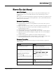
How to Use this Manual Cyber security disclaimer How to Use this Manual About This Manual This manual is written for the owner and user of the Siemens BT300 Bypass. It is designed to help you become familiar with the Siemens BT300 Bypass and its applications. This section covers manual organization, document conventions and symbols used in the manual, how to access help, related publications, and any other information that will help you use this manual.
How to Use this Manual Cyber security disclaimer New terms appearing for the first time are italicized. The field panel continuously executes a user-defined set of instructions called the control program. This symbol signifies Notes. Notes provide additional information or helpful hints. Cross references to other information are indicated with an arrow and the page number, enclosed in brackets: [→92] For more information on creating flowcharts, see Flowcharts [→92].
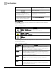
How to Use this Manual Reference Documents Warning Type Description NOTE Notes provide additional information or helpful hints. Les remarques fournissent des informations supplémentaires ou des conseils utiles. Getting Help For more information about BT300 products, contact your local Siemens Industry representative. Reference Documents The following documentation is available from your local Siemens Industry, Inc.
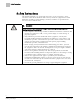
Safety Instructions Safety Instructions The following guidelines are provided for your safety, to prevent damage, and to extend the service life of the BT300 Drive and any connected equipment. Read this information carefully. Specific Warnings, Cautions, and Notes are provided in the relevant sections of this manual. WARNING The BT300 Drive uses hazardous voltages and controls potentially dangerous rotating mechanical components.
Safety Instructions WARNING Le variateur Siemens BT300 utilise des tensions dangereuses et commande des pièces mécaniques rotatives potentiellement dangereuses. ● ● ● ● ● ● Le non-respect des avertissements et des instructions contenus dans ce manuel peut occasionneré la mort de personnes, des blessures graves, ou des dommages sérieux aux biens et aux équipements.
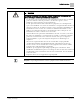
Bypass Overview General Description Bypass Overview General Description During normal operation in a typical application, the input contactor (optional) and output contactor close and the BT300 Drive operates the motor. During bypass operation, the bypass contactor provides the ability to operate the motor on utility power and eliminate the BT300 Drive from the motor control circuit. Figure 1: Bypass Contactor Options.
Bypass Overview Operation Overview – ● ● "Bypass" closes the bypass contactor (M1) and the bypass indicator is energized. – The motor is connected to utility/line power. Remote Bypass Operation (electronic only) – Requires a jumper between the top two pins (REM) of jumper block J7 on the Bypass Diagnostic Board. – "Off" opens the drive output contactor and the bypass contactor.
Start-up Procedures Safety Precautions Start-up Procedures Safety Precautions WARNING Failure to disconnect input power may cause serious injury or death. When you connect input power to the Siemens BT300 Bypass, the motor terminals are energized even if the motor is not running. Do not make any connections with input power connected to the Siemens BT300 Bypass. Disconnect and lock out power to the Siemens BT300 Bypass before servicing it.
Start-up Procedures Start-up Procedure, Conventional Bypass (C-Bypass) Start-up Procedure, Conventional Bypass (C-Bypass) NOTE: Insert an X in the Check column when completed; enter N/A if not used. Step Check Description 1 Verify that all three input phases are connected to the input fuse block (or circuit breaker depending upon model) and that the motor leads are connected to the output terminals of the overload relay only.
Start-up Procedures Start-up Procedure, Conventional Bypass (C-Bypass) Step Check Description 17 Complete any other application specific settings for the site as required. 18 The automatic reset is configured for 30-second intervals and 10 reset attempts. If this is not acceptable, configure the automatic reset settings found in the Parameters (3)/Automatic Reset (3.10) menu for desired settings.
Start-up Procedures Start-up Procedure, Electronic Bypass (E-Bypass) Start-up Procedure, Electronic Bypass (E-Bypass) NOTE: Insert an X in the Check column when completed; enter N/A if not used. Step Check Description 1 Verify that all three input phases are connected to the input fuse block (or circuit breaker depending upon model) and that the motor leads are connected to the output terminals of the overload relay only.
Start-up Procedures Start-up Procedure, Electronic Bypass (E-Bypass) Step Check Description 13 The automatic reset is configured for 30-second intervals and 10 reset attempts. If this is not acceptable, configure the automatic reset settings found in the Parameters (3)/Automatic Reset (3.10) menu for desired settings. 14 The default display has been configured to wait for 2 minutes of keypad inactivity before switching to the multi-monitor display. If this is not acceptable, see Timeout Time (5.7.
Start-up Procedures Quick Commissioning Procedure Quick Commissioning Procedure It is important to use the quick commissioning procedure as listed in the workflow. The wizards are in place to help minimize the startup time. 17 Siemens Industry, Inc.
Start-up Procedures Factory Reset Factory Reset Since it is often unknown if any other users have attempted to run the unit, it is recommended to complete a Factory Reset to return the drive to known factory settings. Do the following to complete a Factory Reset: At the drive keypad, select: User Settings > Parameter Backup > Restore Factory Defa > Activate. The drive restarts, the Siemens splash screen displays, and the Startup Wizard automatically begins. See the Startup Wizard (P1.
Start-up Procedures Startup Wizard (P1.19) Startup Wizard (P1.19) The Startup Wizard prompts you for the essential information needed by the drive so that it can start controlling the output as desired. Once power is connected to the BT300 HVAC Drive, the Startup Wizard should run automatically. If it is not running, it can be activated in the Quick Setup (M1) menu or by completing Restore Factory Defaults (P6.5.
Start-up Procedures Startup Wizard (P1.19) Step Parameter/Question Settings 13 Motor Nom Power (P3.1.1.6) Defines nominal motor power from motor nameplate data. 14 Min Frequency (P3.3.1) Minimum allowed frequency reference. 15 Max Frequency (P3.3.2) Maximum allowed frequency reference. 16 I/O Ctrl Ref (P3.3.3) Selects location of frequency setpoint source when in I/O A control.
Start-up Procedures Bypass Wizard (P1.21) Bypass Wizard (P1.21) The Bypass Wizard is activated in the Quick Setup (M1) menu. The wizard assists with configuring the drive for use with the Conventional or Electronic Bypass options. If the Electronic Bypass option is selected, additional features can be enabled, if desired. The standard I/O is re-mapped for use with the Electronic Bypass option. Additional parameters are available when the Electronic Bypass option is enabled.
Start-up Procedures Communications Configuration If Enabled is selected for Remote Bypass, Step 6 displays. Otherwise, the wizard jumps directly to Step 7. Step Parameter/Question Settings 6 Command Source (P3.5.1.1) Fieldbus CTRL I/O Control 7 Interlock* (P3.2.11) Enabled Disabled If Enabled is selected for Interlock, Step 8 displays. Otherwise, the wizard jumps directly to Step 9. Step Parameter/Question Settings 8 Interlock Delay (P3.2.12) Range: 0 to 120 s 9 Auto Bypass* (P3.18.
Wiring Diagrams Power Wiring Wiring Diagrams Power Wiring Figure 2: Power Wiring. 23 Siemens Industry, Inc.
Wiring Diagrams Electronic Bypass Control Wiring Electronic Bypass Control Wiring Figure 3: Electronic Bypass Drive Terminations. 24 Siemens Industry, Inc.
Wiring Diagrams Conventional Bypass Control Wiring Conventional Bypass Control Wiring Figure 4: Conventional Bypass Drive Terminations. 25 Siemens Industry, Inc.
Wiring Diagrams Motor Rotation Correction Wiring Motor Rotation Correction Wiring Figure 5: Rotation Correction - VFD Correct, Bypass Reversed. Figure 6: Rotation Correction - VFD Reversed, Bypass Correct. Figure 7: Rotation Correction - VFD Reversed, Bypass Reversed. 26 Siemens Industry, Inc.
Operation (Electronic Bypass Only) Drive Mode – Auto Operation (Electronic Bypass Only) The drive powers up in Drive mode. In this mode the drive can be controlled normally from Auto or Hand control place. In the Drive mode the Bypass running relay output signal is off and the drive’s output contactor is energized by closing the relay RO2 on OPT-B5 board. Bypass contactor is open. A relay output signal Drive active is on when the drive is in Drive mode.
Operation (Electronic Bypass Only) Drive Mode – Hand 4. Use the Up and/or Down Arrow buttons to highlight Activate, and then press OK . The unit is now operating in the Drive mode using I/O or Fieldbus control. The display will return to the default display. Drive Mode – Hand Hand mode is used when you want to override the automation system and run the drive in keypad mode. ● You have full control to start/stop the motor, and what the speed reference is from the keypad directly.
Operation (Electronic Bypass Only) OFF Mode 4. Use the Up and/or Down Arrow buttons to highlight Activate, and then press OK . The unit is now operating in Hand mode. The following table outlines the buttons you can use to control the drive. Button Icon Button Name Description Start Start the drive. Stop Stop the drive. Up and Down Arrows Set the desired frequency (changes are immediate). OK Button Once the frequency is set to the desired value, press OK to lock the setting.
Operation (Electronic Bypass Only) Bypass Mode 3. Use the Up and/or Down Arrow buttons to highlight Activate, and then press OK . The unit is now off. It is not being controlled by the drive or the bypass. The motor will not spin. The display will return to the default display. Bypass Mode Bypass mode is used when you want to override the automation system, and have the motor run directly from line voltage at full speed.
Operation (Electronic Bypass Only) Bypass-Specific Parameters Bypass-Specific Parameters The Bypass settings can only be accessed if Bypass (P3.17.4) is set to Electronic. The best way to set this parameter is by executing the Bypass Wizard (P1.21). The bypass settings contain specific information about the Electronic Bypass configuration. These settings are presented in the following table: Table 3: Bypass Settings.
Application Features (Electronic Bypass Only) Bypass-Specific Parameters Application Features (Electronic Bypass Only) During the bypass wizard execution, if the unit is defined to have the Electronic Siemens BT300 Bypass, then the application features can be enabled. When the Electronic Bypass is enabled in the drive, digital inputs and relay outputs are configured automatically as listed below. The Electronic Bypass is enabled by setting the Bypass parameter to Electronic value.
Application Features (Electronic Bypass Only) Bypass-Specific Parameters Figure 8: Electronic Bypass Terminations. 33 Siemens Industry, Inc.
Application Features (Electronic Bypass Only) Standard I/O Assigned for Bypass Standard I/O Assigned for Bypass Digital Input 1: Customer Supplied Run/Stop. Digital Input 2: Remote Safety No. 1. Digital Input 3: Remote Safety No. 2. Digital Input 4: Interlock Feedback (if the interlock function is enabled). Digital Input 5: Overload. Digital Input 6: Essential Services Activation (if the essential services function is enabled). Relay Output 1: Run (default value, no change for bypass option).
Application Features (Electronic Bypass Only) Manual Bypass Delay (P3.18.1, ID: 1818) Manual Bypass Delay (P3.18.1, ID: 1818) This parameter defines the delay when switching between Bypass and Drive manually. Range: 1.0 to 30.0s, Default: 1.0s (as soon as possible). Auto Bypass If the Bypass Wizard was used to configure the Siemens BT300 Bypass and the Auto Bypass feature was enabled, then all required settings are automatically programmed.
Application Features (Electronic Bypass Only) Essential Services Auto Bypass Delay (P3.18.4, ID: 1817) This parameter defines the delay between an active fault and switching to the Bypass. The message Going to Bypass mode displays on the keypad during the delay time. Range: 1.0 to 30.0s, Default: 1.
Application Features (Electronic Bypass Only) Interlock Interlock If the Bypass Wizard was used to configure the Siemens BT300 Bypass and the Interlock feature was enabled, then all required settings will be automatically programmed. The Bypass Wizard can be executed again to enable the Interlock feature, if desired. The Interlock feature (also known as damper end switch logic) enables the BT300 Drive outputs to inhibit motor start until a safety condition (proofing sequence) is confirmed.
Troubleshooting Bypass-Specific Fault Codes Troubleshooting Bypass-Specific Fault Codes Table 4: Fault Codes. Fault Code Fault ID Fault Name Possible Cause Possible Remedy 80 1080 Remote Safety 1 Digital input contact closure is missing. Verify the status of the digital input as defined by Remote Safety 1 (P3.5.1.44). 1180 Remote Safety 2 N/A If not in use, set to a value of DigIN Slot0.2. 1280 Remote Safety 3 N/A Verify the status of the digital input as defined by Remote Safety 2 (P3.5.
Troubleshooting General Bypass Problem Description Possible Cause Drive does not start on closing of the run command. ● The Siemens BT300 Bypass is not in Drive - Auto Mode. ● Drive output contactor is not closed. ● Remote contact is not closed. Replace with jumper to verify. ● Run relay has failed. ● Loose control wire connection. ● The BT300 Drive Digital Input 1 is not programmed properly.
Troubleshooting Electronic Bypass Diagnostic Board Electronic Bypass Diagnostic Board Figure 10: Electronic Bypass Diagnostic Board. 40 Siemens Industry, Inc.
Troubleshooting Electronic Bypass Diagnostic Board Table 5: Expected Voltages, Electronic Bypass Diagnostic Test Points. Expected Voltage Drive Off Bypass/ Essential Services TP8 115 Vac 115 Vac 115 Vac Point between OL1 term 96 and M2A-B terminal 3. TP2 TP8 0 Vac 115 Vac 115 Vac Point between M2A-B terminal 2 and Drive OPT-B5 card terminal 22. TP3 TP8 0 Vac 0 Vac 115 Vac Drive OPT-B5 card terminal 23 (M1 coil power).
Troubleshooting Electronic Bypass Diagnostic Board Figure 11: Electronic Bypass Relay/Diagnostic Board Terminations. 42 Siemens Industry, Inc.
Troubleshooting Conventional Bypass Diagnostic Board Conventional Bypass Diagnostic Board Figure 12: Conventional Bypass Diagnostic Board. 43 Siemens Industry, Inc.
Troubleshooting Conventional Bypass Diagnostic Board Table 6: Expected Voltages, Conventional Bypass Diagnostic Test Points. Test Point Reference Drive Off Bypass Essential Services Description TP1 TP8 0 Vac 0 Vac 115 Vac 115 Vac Point between ESR-B terminal 4 and M2A-B terminal 3. TP2 TP8 0 Vac 0 Vac 115 Vac 115 Vac M1 coil power. TP3 TP8 0 Vac 0 Vac 115 Vac 115 Vac M1 coil power. TP4 TP8 115 Vac 0 Vac 0 Vac 0 Vac Point between ESR-C terminal 7 and M1A-B terminal 3.
Troubleshooting Conventional Bypass Diagnostic Board Figure 13: Conventional Bypass Relay/Diagnostic Board Terminations. 45 Siemens Industry, Inc.
1 Technical Information Product Numbers Technical Information Product Numbers 46 Siemens Industry, Inc.
Technical Information Power Ratings 1 Power Ratings The following chart shows the BT300 HVAC Drive power ratings in accordance with frame sizes: Technical Data Table 7: Drive Specifications. Specification Description Input Voltages and Power Ranges (3-phase) 208 to 240 Vac (-10% to +10%): 1 HP to 125 HP (0.75 kW to 90 kW) 4.2 amps to 301 amps 380 to 500 Vac (-10% to +10%): 1.5 HP to 250 HP (1.1 kW to 160 kW) 3.
1 Technical Information Technical Data Specification Description Circuit Breaker - 65,000 AIC @ 208/240 Vac 18,000 AIC @ 480 Vac Frequency Reference Analog Input Keypad Resolution 0.01 to 0.1% (10 bit), accuracy ±1% Resolution 0.
Technical Information Accessories and Replacement Parts Specification Protection features 1 Description Under-voltage trip limit Over-voltage trip limit Ground fault protection Input (mains) supervision Motor phase supervision Over-current protection Unit over-temperature protection Motor overload protection Motor stall protection Motor underload protection Short-circuit protection of 10 Vdc and 24 Vdc reference voltages Accessories and Replacement Parts Table 8: BT300 HVAC Drive Accessories and Replace
1 Technical Information Accessories and Replacement Parts Accessories Kit BT300-ACCKIT-FS7 BT300-ACCKIT-FS8 BT300-ACCKIT-FS9 EMC Filter Kit BT300-EMCKIT-FS7 N/A BT300-EMCKIT-FS9 Flange Mount Kit BT300-FLG-FS7 N/A N/A Main Fan (heatsink) BT300-MFAN-FS7 BT300-MFAN-FS8 BT300-MFAN-FS9 NEMA 1 Cover BT300-CVR-2154-FS7 BT300-CVR-2154-FS8 N/A NEMA 1 Gland Plate N/A N/A N/A Table 9: Accessories.
Technical Information Accessories and Replacement Parts 1 51 Siemens Industry, Inc.
Issued by Siemens Industry, Inc. Building Technologies Division 1000 Deerfield Pkwy Buffalo Grove IL 60089 Tel. +1 847-215-1000 Document ID DPD01391 Edition 2017-09-28 © Siemens Industry, Inc., 2017 Technical specifications and availability subject to change without notice.