
Operating Instructions


Bypass Overview
Gene
ral Description
10
Siemens Industry, Inc. BT300 Bypass Operator's Manual DPD01391
Building Technologies 2017-09-28
Bypass Overview
General Description
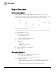
During normal operation in a typical application, the input contactor (optional) and
output contactor close and the BT300 Drive operates the motor.
During bypass operation, the bypass contactor provides the ability to operate the motor
on utility power and eliminate the BT300 Drive from the motor control circuit.
Figure 1: Bypass Contactor Options.
The Siemens BT300 Bypass consists of a BT300 Drive and a bypass enclosure with
controls that include the following:
● Control terminals
● Operators (conventional only):
– "Drive-Off-Bypass" switch
– "Bypass On" light
– "Drive Test On-Off" switch (optional)
● Step-down control transformer
● Contactors:
– Bypass (M1)
– Output (M2)
– Input (M3) or Service Switch
● Overload (current) relay
● Disconnect with fuses, or circuit breaker
● Diagnostics board
Operation Overview
● Drive Mode
– Drive input contactor (M3) or selector switch closes.
– Drive output contactor (M2) closes.
– The motor is controlled by the BT300 Drive output.
● Local Bypass Operation
– Requires a jumper between the bottom two pins (LOC) of jumper block J7 on
the Bypass Diagnostic Board. This is the default jumper position from the
factory.
– "Off" opens the drive output contactor and the bypass contactor.