
Basic Documentation


Startup Procedure and Checklist
Document Number 125-1006
Rev. FA, June 18, 2019
BT300 Variable Frequency Drives
Step
Check
Description
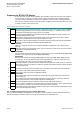
1
Verify that all three input phases are connected to the input fuse block (or circuit breaker depending
upon model) and that the motor leads are connected to the output terminals of the overload relay
only.
Note : The M1 (Bypass) contactor and the M2 (Output) contactor outputs are connected together at the factory.
2
Verify that all factory connections within the bypass are tight as factory connections can loosen
during shipment.
3
Record all connections to the drive in the Slot A&B Terminals sheet of this document.
4
Record all connections to the bypass diagnostics board in the Diag Terminals sheet of this
document.
5
Dial in the current limit on the overload in accordance with the connected motor.
6
Apply power to the drive with e-bypass option. Verify that all three phases are present and that the
input voltage is correct fo the system.
7
The keypad should illuminate and Startup Wizard of the drive should be active. Complete the
Startup Wizard. When prompted for Bypass Wizard, answer YES .
Note: This should be activated when the unit is first powered up. If not , then it is recommend to reset the drive
to factory default to return to a good known starting configuration. This can be completed by navigating to the
following in the menu structure:
User Settings (6)… Parameter Backup (6.5)… Restore Factory Defaults (6.5.1)... Activate
Refer to the Operator's Manual (DPD01149) for detailed information about the Startup Wizard.
8
During the execution of the bypass wizard, select
Electronic
.
Note : A Remote Safety 1 and Remote Safety 2 fault will occur. Press the Back/Reset button once to return to
the wizard. Configure the Remote Safety 1 (3.5.1.44) and Remote Safety 2 (3.5.1.45) once completed with
the bypass wizard. Refer to the Bypass Operator's Manual (DPD01391) for detailed information about the
Bypass Wizard.
9
Press the
HAND/AUTO
button on the drive. Select
Drive
and press the OK button. Select
Hand
and press the OK button. With Activate displayed, press the OK button.
At the drives keypad, enter a setpoint greater than 5 hertz, and then press the green I button to start
the motor. Verify the motor rotation is correct for the application. Press the red O button to stop the
motor.
10
"Bump" the by pressing the
HAND/AUTO
button on the drive. Select
Bypass
and press the
OK
button. With Activate displayed, press the OK button. Then quickly press the HAND/AUTO button
on the drive. Select OFF and press the OK button. With Activate displayed, press the OK button.
Verify the motor rotation is correct for the application.
11
If motor rotation was incorrect in either step 9 or 10, then remove power to the bypass assembly via
the disconnect switch. Wait 5 minutes to allow for the drive's DC Bus to discharge. Make the
required changes as listed in the Bypass Motor Rotation tab of this document. Apply power and
Repeat steps 9 through 10 to verify proper rotation again.
12
Press the
HAND/AUTO
button on the drive. Select
Drive
and press the OK button. Select
Auto
and press the OK button. With Activate displayed, press the OK button.
13
Complete any other required wizards found in the Quick Setup (1) menu.
Refer to the Operator's Manual (DPD01149) for detailed information about the wizards.
14
Complete any other application specific settings for the site as required.
15
The automatic reset is configured for 30 second intervals and 10 reset attempts.
If this is not acceptable, configure the automatic reset settings found in Parameters (3)
…Automatic Reset (3.10) menu for desired settings.
16
The default display has been configured automatically to wait for 2 minutes of keypad inactivity and
then switch to the multi-monitor display. If this is not acceptable, then refer to Timeout Time (5.7.1)
and Default Page (5.7.2) for desired settings.
Startup Procedure for Electronic Bypass Options (BTE…)
Review the Preparing for BT300 VFD Start (tab 2) section in this document.
Place a "X" in the check column when completed. Place a "n/a" if not used.
Page 10
Siemens Industry, Inc.