
Basic Documentation


Startup Procedure and Checklist
Document Number 125-1006
Rev. FA, June 18, 2019
BT300 Variable Frequency Drives
In order to provide you with the most reliable drive available, and to avoid any extra costs related to
loss or reduction of warranty coverage, a factory-certified specialist should complete the startup
procedure. Please complete the checklist and maintain it in a secure location as technical service
personnel may request information from this checklist. Inability to provide this information may result
in delays and extra costs to the end user.
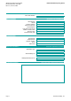
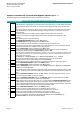
Step
Check
Description
1
The BT300 is thoroughly tested at the factory. Verify that the drive is free of shipping and installation
damage. Shipping damage is not covered by the Siemens Industry, Inc. warranty; claims must be
filed directly with the shipping company as soon as possible.
2
Review the BT300 Installation Instructions and Operator's Manual. Review option intructions and
schematics shipped with the drive.
3
Verify that the model numbers and the voltage ratings are as specified in the purchase order by
matching the nameplate data for each unit to the purchase order.
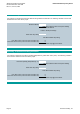
4
Verify that the drive has been installed in accordance with the mechanical and electrical installation
sections in the Siemens BT300 Installation Manual (DPD01148).
CAUTION:
Failure to comply with mechanical and electrical installation requirements may void the product
warranty.
5
Inspect the security of the supply line power, ground connections, and all control circuit connections
as identified in the BT300 documents.
IMPORTANT:
Confirm that the incoming line power supply connects to the drive input terminals (L1(r), L2(s), L3(t)
)
and NOT to the output motor terminals (T1(u), T2(v), T3(w)).
IMPORTANT:
Double check all power wires (L1(r), L2(s), L3(t)) and motor wires (T1(u), T2(v), T3(w)) to make
sure that they are securely tightened down to their respective lugs. Loose wire connections may
cause problems at any time, and are not covered under warranty.
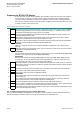
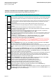
6
Review the installer's "as-wired" schematic. Determine where the motor "safety circuit" is connected.
Verify that the customer's emergency contacts are properly terminated in the drive's safety shutdown
circuit or bypass panel.
7
Record the motor's name plate information (in the motor & drive information tab of this workbook).
8
Verify that the input voltage matches the drive's rating.
9
Verify that the motor is wired for the application voltage.
10
IMPORTANT:
Verify that the motor rated full load amps (FLA) does NOT exceed the rated output current of the
drive controlling it.
When multiple motors are simultaneously operated by the drive, the sum of all motor rated FLA
values must be less than or equal to that of the drive controlling them.
11
Record the application type (in the motor & drive information tab of this workbook).
12
Record any other connections to the drive by terminal number to determine if special programming is
required (note any changes in the SlotA&B Terminals tab of this workbook)
13
If applicable, verify that the building automation system logic is ready to perform adequately for start,
stop, and speed reference functions.
Place a "X" in the "check" column when completed.
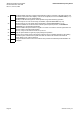
Preparing for BT300 VFD Startup
This concludes the preparation process for BT300 VFD Startup.
Keep your BT300 Installation and Operator's documentation, option schematics, and any other instructions sent
with the drive easily accessible to assist you through the remainder of this startup process.
Page 6 Siemens Industy, Inc.