
Data Sheet for Product

Page 6 of 16
Siemens Industry, Inc.
Specifications, Continued
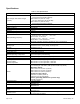
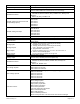
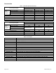
Table 2. Control Board Technical Specifications.
Slot A
Terminal
Signal/Description
Specification
1
+10 Vdc Reference Output
+3%; Maximum current 10 mA
2
Analog Input 1 Signal (+)
0 to 10 Vdc (200K Ohm) or 0 to 20 mA (250K Ohm)
(selection using DIP switch)
Resolution: 0.1%, Accuracy: ±1%; Short-circuit protected.
3
Analog Input 1 Common (-)
4
Analog Input 2 Signal (+)
0 to 10 Vdc (200K Ohm) or 0 to 20 mA (250K Ohm)
(selection using DIP switch)
Resolution: 0.1%, Accuracy: ±1%; Short-circuit protected.
5
Analog Input 2 Common (-)
6
24 Vdc Output Voltage
±10%; Maximum 250 mA;
Short-circuit protected.
7
I/O Ground
8
Digital Input 1
Positive or negative logic;
0 Vdc to 5 Vdc = 0; 15 Vdc to 30 Vdc = 1
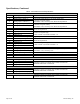
9
Digital Input 2
10
Digital Input 3
11
Common for DI 1 through DI 6
Digital inputs can be isolated from ground.
12
24 Vdc Output Voltage
±10%; Maximum 250 mA;
Short-circuit protected.
13
I/O Ground
14
Digital Input 4
Positive or negative logic;
0 Vdc to 5 Vdc = 0; 15 Vdc to 30 Vdc = 1
15
Digital Input 5
16
Digital Input 6
17
Common for DI 1 through DI 6
Digital inputs can be isolated from ground.
18
Analog Output 1 Signal (+)
0 to 10 Vdc or 0 to 20 mA (selection using DIP switch)
Resolution: 0.1%, Accuracy: ±1%
19
Analog Output 1 Common (-)
30
24 Vdc Input Voltage
±10%; Maximum 250 mA; Used for power backup of control unit.
A
RS-485 -
Fieldbus Negative
B
RS-485 +
Fieldbus Positive
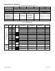
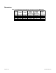
Slot B
Terminal
Signal/Description
Specification
21
Relay Output 1 Normally Closed
Switching capacity: 24 Vdc/8A; 250 Vac/8A; 125 Vdc/0.4A
Minimum switch load: 5 Vdc/10 mA
22
Relay Output 1 Common
23
Relay Output 1 Normally Open
24
Relay Output 2 Normally Closed
Switching capacity: 24 Vdc/8A; 250 Vac/8A; 125 Vdc/0.4A
Minimum switch load: 5 Vdc/10 mA
25
Relay Output 2 Common
26
Relay Output 2 Normally Open
32
Relay Output 2 Common
Switching capacity: 24 Vdc/8A; 250 Vac/8A; 125 Vdc/0.4A
Minimum switch load: 5 Vdc/10 mA