Building Automation – Impact on energy efficiency Application of EN 15232-1:2017 siemens.
Table of contents 1 Introduction ................................................................................................................... 3 1.1. Use, targets and benefits ................................................................................................ 3 1.2. What constitutes energy efficiency?................................................................................ 4 2 Global situation: energy and climate ..............................................................
6 Energy efficiency from Siemens .............................................................................. 135 6.1. 6.1.1. 6.1.2. Building Automation solutions from Siemens .............................................................. 135 Building automation and control Systems ................................................................... 135 HVAC products to create perfect places ..................................................................... 136 6.2.
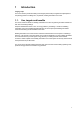
1 Introduction Target groups This User’s Guide by Siemens Building Technologies (Siemens BT) is targeted at all participants in the planning phases for buidlings and, in particular, building automation and control. 1.1. Use, targets and benefits The User’s Guide was written for building automation and control engineering and sales activities for both new and existing buildings.
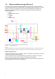
1.2. What constitutes energy efficiency? The ratio of energy input to the calculated or estimated amounts of energy required to cover the various requirements relating to the standardized use of a building serves as the measure of energy efficiency.
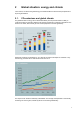
2 Global situation: energy and climate In this section, we discuss the global energy and climate situation as well as future perspectives on improving the situation. 2.1. CO2-emissions and global climate The global demand for energy has increased dramatically over the past decade and is likely to continue according to forecasts. Within the percentage of fossil fuels, oil is likely to stagnate or even decline in the future, while natural gas and coal are projected to increase significantly.
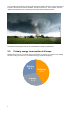
The consequences include an increase in storm winds and storms, damage to crops and forests, an increase in the sea level as well as mudslides, droughts and erosions – so for example, hurricane “Katrina” (New Orleans) or the continuously returning tornados in Oklahoma (USA): Tornado in Oklahoma (Source: tagesschau.de) The Climate Change Report 2007 by the United Nations is calling for global action. 2.2.
2.3. Turning the tide – a long-term process Europe has developed visions for a low-energy future and is intensely searching for ways to implement the visions: Vision for the future We want to find ways to continue enjoying our lives in reasonable comfort, but using less energy, and with fewer CO2 and greenhouse emissions than today. The scenario "Paths toward a 2,000 watt society" as part of Swiss energy policies pursues goals that are similar to current efforts at the EU level.
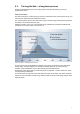
2.4. Reduce energy usage in buildings Well-developed building construction standards are now available for low-energy houses that have proven themselves. The technology is ready to use – yet it is still going to take a number of decades before the technology is deployed throughout Europe. New buildings New buildings should only be built based on future-oriented low-energy standards and equipped with energy-saving building automation and control functions of BAC efficiency class A.
Source: Novatlantis – Sustainability within the ETH Overall energy usage should be decreased by reducing the primary energy use for the building within the red intersecting region. Energy saving potential with building automation and control Building automation and control systems are the building’s brain. They integrate the information for all the building’s technology.
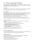
2.5. Siemens’ contribution to energy savings We are taking the initiative Siemens feels an obligation to assist its customers in improving the energy efficiency of their buildings. As a consequence, Siemens is a member of a number of global initiatives.
German industry can make a number of contributions to climate protection and is therefore a problem solver. To underscore the German economy's commitment to climate protection, a number of leading business people came together under the auspices of the Association of German Industry on the initiative "Business for climate change"., With more than 40 companies (and Siemens being one of them), the initiative represents the entire spectrum and abilities of the productive economy in Germany.
3 Building automation and control system standards This section discusses EU measures and goals with regard to energy and the environment, as well as the process and new standards intended to grasp and disarm the energy situation. 3.1. EU measures Energy is a central concern of the EU Dependency Without taking actions, dependency on foreign energy will climb to 70% by 2020/2030.
Environment Energy production and consumption cause some 94% of CO2 emissions. Supply Influence on energy supply is limited. Price Significant increase within a few short years, but subject to strong geopolitical changes.
This Directive lays down requirements regarding: (a) (b) (c) (d) (e) the general framework for a methodology of calculation of the integrated energy performance of buildings the application of minimum requirements on the energy performance of new buildings the application of minimum requirements on the energy performance of large existing buildings (> 1000 m2) that are subject to major renovation Energy certification of buildings regular inspection of boilers and of air conditioning systems in buildings an
CEN / TC 247 CEN / TC 247 develops European and international standards for building automation, controls and building management (BACS), for instance: · · · · · Product standards for electronic control equipment in the field of HVAC applications (e.g. EN 15500) à Basis for product certification related to EPBD Standardization of BACS functions (EN ISO 16484-3) à Basis for the impact of BACS on energy efficiency Open data communication protocols for BACS (e.g.
3.2. The standard EN 15232 What is EN 15232? A new European standard EN 15232: "Energy performance of buildings - Impact of Building Automation, Control and Building Management" is one of a set of CEN (Comité Européen de Normalisation, European Committee for Standardization) standards, which are developed within a standardization project sponsored by the EU.
eu.bac Cert guarantees users a high level of · · energy efficiency, and product and system quality as defined in the corresponding EN/ISO standards and European Directives. Some public organizations approve only eu.bac-certified products. 3.3.1. eu.bac System Certification In addition to the product certification, eu.bac has developed and launched a systematic approach to assess and certify complete building automation system solutions in a building.
4 The EN 15232 standard in detail EN 15232 makes it possible to qualify and quantify the benefits of building automation and control systems. The entire standard is based on building simulations using pre-defined building automation and control functions. Parts of the standard can be used directly as a tool to qualify the energy efficiency of building automation and control projects. It is also planned to assign projects to one of the standard energy efficiency classes A, B, C or D.
Key: [1] [2] [3] [4] [5] [6] [7] [8] [9] is the energy needed to fulfill the user's requirements for heating, lighting, cooling etc., according to levels that are specified for the purposes of the calculation are the "natural" energy gains – passive solar, ventilation cooling, daylight, etc. together with internal gains (occupants, lighting, electrical equipment, etc.
The building automation and control functions described in sections 4.1 and 4.2 are aligned in accordance with the energy demand and supply model. The relevant energy efficiency functions are handled starting with the room via distribution up to generation. The following graphic show the cross-dependencies between functions in the room (e.g. Heating 1.1, Cooling 2.1) and functions of the distribution and generation for heating, cooling, ventilation and hot water (e.g. heat pump 1.7, ventilation plant 4.5).
Space heating system 1.10 1.6, 1.7, 1.8, 1.9 Key 1 2 3 4 5 6 heat generator thermal energy storage air handling unit room heating water supply heating water return NOTE The numbers 1.1 through 1.9 refer to the numbers in the tables in Chapter 4. Domestic hot water heating system 2.3 2.4 2.2 2.1 Key 1 2 3 4 5 solar collector boiler/district heating heat pump domestic hot water storage heating water supply heating water return NOTE The numbers 2.1 through 2.
Cooling system Key 1 2 3 4 5 6 solar collector thermal energy storage air handling unit room heating water heating water return NOTE The numbers 3.1 through 3.9 refer to the numbers in the tables in Chapter 4. Split system/VRF (heating and/or cooling) Key 1 2 3 4 outdoor unit indoor unit room 1 room 2 NOTE 22 The numbers 1.1 through 3.6 refer to the numbers in the tables in Chapter 4.
Ventilation and air-conditioning System Key 1 2 3 4 5 6 7 8 exhaust air outside air room variable air volume chilled water supply chilled water return heating water heating water return NOTE The numbers 4.1 through 4.10 refer to the numbers in the tables in Chapter 4. 4.1. List of relevant building automation and control functions Energy efficiency-relevant functions and possible processing functions for building automation and control systems are the focus of EN 15232.
1 2 4 5 1 2 3 4 5 On the following pages are · · à 24 Right side: Left side: Tables from EN 15232 and reason for energy saving Remarks of Siemens BT Continued on the next double page
25
Remarks of Siemens This section outlines how Siemens interprets the functions and processing functions according to EN 15232-1:2017. 1) Plants required for "emission control" of thermal energy (e.g. radiators, chilled ceilings, VAV systems) may have different supply media (e.g. water, air, electricity). As a result, different BAC solutions may be possible for a processing function.
AUTOMATIC CONTROL 1 HEATING CONTROL 1.1 Emission control BT Reason for energy savings 1 The control system is installed at the emitter or room level, for case 1 one system can control several rooms. 0 No automatic control of the room temperature The highest supply output is continuously delivered to the heat emitters resulting in the supply of unnecessary thermal energy under part load conditions.
Remarks of Siemens This section outlines how Siemens interprets the functions and processing functions according to EN 15232-1:2017.
AUTOMATIC CONTROL 1 HEATING CONTROL 1.2 Emission control of TABS (heating mode) 0 No automatic control of the room temperature 1 Central automatic control BT 5 The highest supply output is continuously delivered to the TABS, resulting in the supply of unnecessary thermal energy under part load conditions. 6 Supply output is controlled depending on the outside temperature, for example (corresponding to the probable heat demand of the consumers).
Remarks of Siemens This section outlines how Siemens interprets the functions and processing functions according to EN 15232-1:2017. 8) The pump is only released on demand. With proportional Dp: Pump solutions with an external differential measurement (e.g. based on the effective load by the consumer) are more expensive overall. They do, however, allow for more precise pump control than pumps with integrated pressure control equipment.
AUTOMATIC CONTROL 1 HEATING CONTROL 1.3 Control of distribution network hot water temperature (supply or return) BT Reason for energy savings Similar function can be applied to the control of direct electric heating networks 0 No automatic control The highest design temperature of all consumers is continuously provided in distribution, resulting in significant energy losses under part load conditions.
Remarks of Siemens This section outlines how Siemens interprets the functions and processing functions according to EN 15232-1:2017. 9) The Coefficient of Performance (COP) and the Seasonal Energy Efficiency Ratio (SEER) of heat pump plants are positively influenced on the one hand by lower flow water temperatures, while also benefiting from a small temperature differential between evaporator and condenser.
AUTOMATIC CONTROL 1 HEATING CONTROL 1.5 Intermittent control of emission and/or distribution 0 One controller can control different rooms/zones having same occupancy patterns No automatic control 1 Automatic control with fixed time program BT No savings, since emission and/or distribution are permanently in operation. Savings in emission and/or distribution outside the nominal operating hours.
Remarks of Siemens This section outlines how Siemens interprets the functions and processing functions according to EN 15232-1:2017. No specific remarks here.
AUTOMATIC CONTROL 1 HEATING CONTROL 1.8 Heat generator control (outdoor unit) BT Reason for energy savings The goal consists generally in maximizing the heat generator efficiency 1.9 0 On/Off-control of heat generator The delivered heat from the heat generator can only roughly be adjusted to the needs of the consumers. The adjustment mainly happens by changing the switching frequency. This results in reduced efficiency of the heat generator.
Remarks of Siemens This section outlines how Siemens interprets the functions and processing functions according to EN 15232-1:2017. 1) As a rule, DHW heating with storage tank is considered since considerable energy losses may arise for improper solutions. Instantaneous flow heaters close to the consumers are normally operated based on demand and have limited automation functions.
AUTOMATIC CONTROL 2 DOMESTIC HOT WATER SUPPLY CONTROL Term: Function Charging time release: Storage charging time release by time switch program Multi-sensor storage management: Demandoriented storage management using two or more temperature sensors Heat generation: Boilers (fired with different types of fuels), heat pump, solar power, district heating, CHP.
Remarks of Siemens This section outlines how Siemens interprets the functions and processing functions according to EN 15232-1:2017. 3) The hot water circulation pipe from the storage tank to the consumer loses a lot of energy when continuously operating. The storage tank temperature drops due to the continuous energy losses. Frequent recharging is required to cover the losses.
AUTOMATIC CONTROL 2 DOMESTIC HOT WATER SUPPLY CONTROL 2.3 Control of DHW storage charging with solar collector and supplementary heat generation DHW storage tank with two integrated heat exchangers. 0 Manual control Control is affected via thermostat. The generator must be preselected: 1 Automatic control of solar storage charge (Prio. 1) and supplementary storage charge (Prio.
Remarks of Siemens This section outlines how Siemens interprets the functions and processing functions according to EN 15232-1:2017. 1) The Plants required for "emission control" of thermal energy, such as fan coils, chilled ceilings or VAV systems may have different supply media (e.g. water, air). As a result, different BAC solutions may be possible for a processing function.
AUTOMATIC CONTROL 3 COOLING CONTROL 3.1 Emission control 0 The control function is applied to the emitter (cooling panel, fan-coil unit or indoor unit) at room level; for type 1 one function can control several rooms No automatic control of the room temperature 1 Central automatic control BT 1 The highest supply output is continuously delivered to the heat exchangers, resulting in the supply of unnecessary thermal energy under part load conditions.
Remarks of Siemens This section outlines how Siemens interprets the functions and processing functions according to EN 15232-1:2017.
AUTOMATIC CONTROL 3 COOLING CONTROL 3.2 Emission control for TABS (cooling mode) 0 1 BT 5 No automatic control of the room temperature Central automatic control The highest supply output is continuously delivered to the TABS, resulting in the emission of unnecessary cooling energy under part load conditions. 6 Supply output is controlled depending on the outside temperature, for example (corresponding to the probable heat demand of the consumers).
Remarks of Siemens This section outlines how Siemens interprets the functions and processing functions according to EN 15232-1:2017. 8) The pump is only released on demand. With proportional Dp: Pump solutions with an external differential measurement (e.g. based on the effective load by the consumer) are more expensive overall. They do, however, allow for more precise pump control than pumps with integrated pressure control equipment.
AUTOMATIC CONTROL 3 COOLING CONTROL 3.3 Control of distribution network cold water temperature (supply or return) BT Grund der Energieeinsparung Similar function can be applied to the control of direct electric cooling (e.g. compact cooling units, split units) for individual rooms 0 1 Constant temperature control A constant, low design temperature of all consumers is continuously provided in distribution, resulting in significant energy losses under part load conditions.
Remarks of Siemens This section outlines how Siemens interprets the functions and processing functions according to EN 15232-1:2017. 9) In buildings with air conditioning systems is this an important function regarding energy savings. The possibility to cool and heat a room at the same time depends on the system setup and the automation functions. Depending on the system setup, a complete interlock can be achieved with a simple automation function, or a complex automation function might be required.
AUTOMATIC CONTROL 3 COOLING CONTROL 3.5 Intermittent control of emission and /or distribution BT Reason for energy savings One controller can control different rooms/zones having same occupancy patterns 0 1 No automatic control No savings, since emission and/or distribution are permanently in operation. Automatic control with fixed time program Savings in emission and/or distribution outside the nominal operating hours.
Remarks of Siemens This section outlines how Siemens interprets the functions and processing functions according to EN 15232-1:2017. No special remarks here.
AUTOMATIC CONTROL 3 COOLING CONTROL 3.7 Different chillers selection control BT Reason for energy savings The goal consists generally in maximizing the chiller water temperature 3.8 0 Constant temperature control With that a low chilled water temperature will always be provided independent from the demand. This results in an unnecessarily high energy consumption at the chiller(s).
Remarks of Siemens This section outlines how Siemens interprets the functions and processing functions according to EN 15232-1:2017. No special remarks here.
AUTOMATIC CONTROL 3 COOLING CONTROL 3.9 Control of Thermal Energy Storage (TES) charging BT Reason for energy savings The TES is part of the cooling/chilled water system. 0 Continuous storage operation This is mainly to ensure supply in case of a chiller failure. By continuously storing chilled water there is also a continuous loss (by absorbing heat from the surroundings) at the storage tank.
Remarks of Siemens This section outlines how Siemens interprets the functions and processing functions according to EN 15232-1:2017. 1) Here only air renewal in the room is considered. Note: For the room temperature control the parts “Heating control” and “Cooling control” of the EN 15232 are to be considered. 2) Here only the approach how the room temperature is controlled via the supplied air flow and the supply air temperature is of importance.
AUTOMATIC CONTROL 4 VENTILATION AND AIR CONDITIONING CONTROL BT Reason for energy savings This section is for building energy systems that bring air into the building: both ventilation and air conditioning systems. Heating and Cooling of air requires additional heating and cooling devices. Control functions related to heating/cooling systems are defined in sections 1 and 3 resp. 4.1 Supply air flow control at the room level (e.g.
Remarks of Siemens This section outlines how Siemens interprets the functions and processing functions according to EN 15232-1:2017. 3) With that it will be prevented that two control loops attempt to control the same control value. This means e.g. the room heating is set to bring the room temperature to 15 °C, the supply air temperature will then be provided depending on the room temperature in order to maintain the desired room temperature. With that internal heat gains (e.g.
AUTOMATIC CONTROL 4 VENTILATION AND AIR CONDITIONING CONTROL 4.3 Coordination of room air temperature control by ventilation and by static system BT Reason for energy savings Interaction of the different systems has to be coordinated. 0 Interaction is not coordinated: Without coordination there is a risk of having independent control loops working against each other and inner and external heat gains cannot be taken into account.
Remarks of Siemens This section outlines how Siemens interprets the functions and processing functions according to EN 15232-1:2017. 5) By switching stages the speed n of the fans and with that the air flow V̇ will be changed. With that the power consumption of the fans changes too. For that, the following proportional (or affinity) laws apply: 3 n1 V̇ 1 P1 V̇ 1 P1 n1 3 = und = resp.
AUTOMATISCHE REGELUNG 4 VENTILATION AND AIR CONDITIONING CONTROL 4.5 Air flow or pressure control at the air handler level 0 No automatic control: BT When the air handling unit is in operation, always the maximally required air flow will be conditioned and transported. This leads to a correspondingly high energy consumption for conditioning and transporation. The air handling unit can also be in operation even if it is not required. Continuously supplies of air flow for a maximum load of all rooms.
Remarks of Siemens This section outlines how Siemens interprets the functions and processing functions according to EN 15232-1:2017. 10) This is often the case in plants where separate (independent) control loops are utilized for the heat recovery and the pre-heating and heating coils. 11) This is today’s typical solution that utilizes heating/cooling sequences of the temperature control loop appropriately.
AUTOMATIC CONTROL 4 VENTILATION AND AIR CONDITIONING CONTROL 4.7 Heat recovery control (prevention of overheating) BT Reason for energy savings 10 Heat recovery is always on 100% and can overheat the supply air flow, requiring additional energy for cooling. 11 Temperature sequence control at heat recovery prevents unnecessary recooling of the supply air. This control function is to avoid overheating at the heat recovery unit.
Remarks of Siemens This section outlines how Siemens interprets the functions and processing functions according to EN 15232-1:2017. No special remarks here.
AUTOMATIC CONTROL 4 VENTILATION AND AIR CONDITIONING CONTROL 4.9 Supply air temperature control at the AHU level BT Reason for energy savings There might be several supply air temperatures in an air conditioning system: the supply air temperature at the outlet of the AHU, the supply air temperature at the outlet of central re-heaters as well as supply air temperature at the room level (terminal re-heat boxes).
Remarks of Siemens This section outlines how Siemens interprets the functions and processing functions according to EN 15232-1:2017. 13) Precondition for dew point control is an air humidifier (air washer) with a humidification efficiency of at least 95 %, by that practically reaching a fully saturated air condition. By controlling to the temperature of this saturated air the humidity content is also fixed. The required control infrastructure for it is relatively small.
AUTOMATIC CONTROL 4 VENTILATION AND AIR CONDITIONING CONTROL 4.10 Humidity control BT Grund der Energieeinsparung The control of the air humidity may include humidification and / or dehumidification. Controllers may be applied as "humidity limitation control" or "constant control". 0 No automatic control The humidity of the central supply air is not affected. No control loop enables to act on the air humidity.
Remarks of Siemens This section outlines how Siemens interprets the functions and processing functions according to EN 15232-1:2017. 1) A warning function overrides the turn-off signal by the user when using a scheduler to turn off lighting. For switchable lights, they are flashed on/off and turned off after a grace period unless overridden by a user. For dimmable lights, they are dimmed to a preset warning level and turned off after a grace period unless overridden by a user.
AUTOMATIC CONTROL 5 LIGHTING CONTROL 5.1 Occupancy control 0 BT Reason for energy savings Manual on/off switch Reducing lighting to occupancy times or current needs in room areas saves energy. In residential buildings The luminaire is switched on and off with a manual switch in the room Users can turn the lighting on and off as needed. This saves lighting energy. In non-residential buildings 1 Lighting is mostly on.
Remarks of Siemens This section outlines how Siemens interprets the functions and processing functions according to EN 15232-1:2017. 3) Daylight harvesting based on closed-loop automatic light-level control in combination with presence detection (modes: Manual On/Dimmed (Off) or Manual On/Auto Off) using a sensor in the room is a simple way to integrate automated blinds control.
AUTOMATIC CONTROL 5 LIGHTING CONTROL 5.2 Light level / Daylight control (daylight harvesting) 0 BT Artificial lighting can be reduced as the incoming daylight increases, thus saving energy. Luminaires will be manually adjusted from a central point when the day light level becomes too low. However, the luminaires often will not be reduced when the day light is at a sufficient level (sub optimal).
Remarks of Siemens This section outlines how Siemens interprets the functions and processing functions according to EN 15232-1:2017. 1) Reasons for blind control: - Reduces external light can prevent blinding room users. - Reduces heat radiation in the room saves cooling energy. - Allowing heat radiation in the room saves heating energy. - Closed blinds reduce heat loss in the room.
AUTOMATIC CONTROL 6 BLIND CONTROL There are two different motivations for blind control: solar protection to avoid overheating and to avoid glaring 0 BT 1 Manual operation Usually, manual interventions are only made for glare protection. Energy savings are highly dependent on user behavior. Mostly used only for manual shadowing, energy saving depends only on the user behavior 1 Motorized support only eases manual intervention and is mostly only done for glare protection.
Remarks of Siemens This section outlines how Siemens interprets the functions and processing functions according to EN 15232-1:2017. No special remarks here.
AUTOMATIC CONTROL 7 TECHNICAL HOME AND BUILDING MANAGEMENT BT Reason for energy savings The Technical Home and Building Management enables to adapt easily the operation to the user needs. One shall check at regular intervals that the operation schedules of heating, cooling, ventilation and lighting is well adapted to the actual used schedules and that the set points are also adapted to the needs.
Remarks of Siemens This section outlines how Siemens interprets the functions and processing functions according to EN 15232-1:2017. 1) Errors, deviations, etc., are automatically determined and reported, making it possible to eliminate less-than-efficient operation as early as possible.
AUTOMATIC CONTROL 7 TECHNICAL HOME AND BUILDING MANAGEMENT 7.2 Manual setting room by room individually BT Reason for energy savings Adaptation of system/plant operating hours according to given time schedule and/or calendar 7.3 7.4 0 Manual setting (plant enabling) 1 Individual setting following a predefined schedule including fixed preconditioning phases 2 Individual setting following a predefined time schedule; adaptation from a central room (e.g.
Remarks of Siemens This section outlines how Siemens interprets the functions and processing functions according to EN 15232-1:2017. 3) Local energy sources and energy production provide for a reduction of energy consumption from the net and therefore contribute to the reduction of superordinate produced energy (power plants) and with that contribute to the energy transition. 4) Heat recovery and heat shifting reduce the consumption of primary energy.
AUTOMATIC CONTROL 7 TECHNICAL HOME AND BUILDING MANAGEMENT 7.5 Local energy production and renewable energy BT Reason for energy savings 3 Managing local renewable energy sources and other local energy productions as CHP 7.6 7.
4.2.
Function classification list The function classification list below contains 11 columns: Columns 1 to 11 correspond to the content of EN 15232-1:2017 · · Number of BACS and TBM functions Field of use and the corresponding numbers for possible processing functions · Column 3 Processing functions for evaluation · In columns 4 to 7 Each processing function is assigned a BAC energy efficiency class for residential buildings.
Remarks of Siemens This section outlines how Siemens interprets the functions and processing functions according to EN 15232-1:2017. 1.1 Plants and installations required for "emission control" of thermal energy, such as radiators, chilled ceilings or VAV systems, may use different supply media (e.g. water, air, electricity). As a result, different BAC solutions may be possible for a processing function.
Definition of classes Residential D C B Non residential A D C B A AUTOMATIC CONTROL 1 HEATING CONTROL 1.
Remarks of Siemens This section outlines how Siemens interprets the functions and processing functions according to EN 15232-1:2017. 1.8 1 With several capacity stages, the heat production can be provided according to the demand to a certain degree. 2 With variable control the produced heat can always be provided according to the demand. 1.9 0 Setting priorities based on run times has the focus of a controlled usage (e.g. evenly). The influence on the energy consumption is very minimal.
Definition of classes Residential D C B Non residential A D C B A AUTOMATIC CONTROL 1 HEATING CONTROL 1.8 Heat generator control (outdoor unit) 0 On/Off-control of heat generator 1 Multi-stage control of heat generator 2 Variable control of heat generator 1.9 Sequencing of different heat generators 0 1 2 3 1.
Remarks of Siemens This section outlines how Siemens interprets the functions and processing functions according to EN 15232-1:2017. 2 As a rule, DHW heating with storage tank is considered since considerable energy losses may arise for improper solutions. Instantaneous water heaters close to the consumers are normally operated based on demand and have limited automation functions. 2.2 1 A defined charging time can minimize the amount of time a higher generation temperature is required for DHW charging.
Definition of classes Residential D C B Non residential A D C B A AUTOMATIC CONTROL 2 DOMESTIC HOT WATER SUPPLY CONTROL 2.1 Control of DHW storage temperature with integrated electric heating or electric heat pump 0 Automatic control on/off 1 Automatic control on/off and scheduled charging enable 2 Automatic control on/off and scheduled charging enable and multi-sensor storage management 2.
Remarks of Siemens This section outlines how Siemens interprets the functions and processing functions according to EN 15232-1:2017. 3.1 Plants required for "emission control" of thermal energy such as fan coils, chilled ceilings or VAV systems, may have different supply media (e.g. water, air, electricity). As a result, different BAC solutions may be possible for a processing function.
Definition of classes Residential D C B Non residential A D C B A AUTOMATIC CONTROL 3 COOLING CONTROL 3.1 Emission control The control function is applied to the emitter (cooling panel, fan-coil unit or indoor unit) at room level; for type 1 one function can control several rooms 3.
Remarks of Siemens This section outlines how Siemens interprets the functions and processing functions according to EN 15232-1:2017. 3.8 0 Setting priorities based on run times has the focus of a controlled usage (e.g. evenly). The influence on the energy consumption is very minimal. 1 With that the production is according to demand, however without considering producer features. 2 With that the most efficient producer for a specific operational situation is utilized.
Definition of classes Residential D C B Non residential A D C B A AUTOMATIC CONTROL 3 COOLING CONTROL 3.8 Sequencing of different chillers 0 1 2 3 3.
Remarks of Siemens This section outlines how Siemens interprets the functions and processing functions according to EN 15232-1:2017. 4.1 Here only air renewal in the room is considered. Note: For the room temperature control the parts “Heating control” and “Cooling control” of the EN 15232 are to be considered. 4.3 1 With that it will be prevented that two control loops attempt to control the same control value. This means e.g.
Definition of classes Residential D C B Non residential A D C B A AUTOMATIC CONTROL 4 VENTILATION AND AIR CONDITIONING CONTROL 4.1 Supply air flow control at the room level 0 No automatic control 1 Time control 2 Occupancy detection 4.2 Room air temp. control (all-air systems) 0 on-off control 1 variable control 2 Demand control 4.3 Room air temp. control (Combined air-water systems) 0 No coordination 1 Coordination 4.4 Outside air (OA) flow control 0 1 2 3 4.
Remarks of Siemens This section outlines how Siemens interprets the functions and processing functions according to EN 15232-1:2017. 4.6 1 When cooling the extract air for heat recovery purposes the humidity contained in the air can condensate. At low temperatures this condensate can freeze at the heat exchanger surface. Because of this the free cross-section for the air flow through the heat exchanger can be partially or completely closed off.
Definition of classes Residential D C B Non residential A D C B A AUTOMATIC CONTROL 4 VENTILATION AND AIR CONDITIONING CONTROL 4.6 Heat recovery control: icing protection 0 Without icing protection 1 With icing protection 4.7 Heat recovery control: prevention of overheating 0 Without overheating control 1 With overheating control 4.8 Free mechanical cooling 0 1 2 3 4.9 Supply air temperature control 0 1 2 3 4.
Remarks of Siemens This section outlines how Siemens interprets the functions and processing functions according to EN 15232-1:2017. 5.1 2 A warning function overrides the turn-off signal by the user when using a scheduler to turn off lighting. For switchable lights, they are flashed on/off and turned off after a grace period unless overridden by a user. For dimmable lights, they are dimmed to a preset warning level and turned off after a grace period unless overridden by a user.
Definition of classes Residential D C B Non residential A D C B A AUTOMATIC CONTROL 5 LIGHTING CONTROL 5.1 Occupancy control 0 1 2 3 5.
Remarks of Siemens This section outlines how Siemens interprets the functions and processing functions according to EN 15232-1:2017. 7.3 1 Errors, deviations, etc., are automatically determined and reported, making it possible to eliminate less-than-efficient operation as early as possible. 7.
Definition of classes Residential D C B Non residential A D C B A AUTOMATIC CONTROL 7 TECHNICAL HOME AND BUILDING MANAGEMENT 7.1 Setpoint management 0 1 2 3 7.
4.2.1. Procedure for meeting an efficiency class for BACS projects Example: Single room store The building contains an open single room store that is air conditioned using a central air handling unit. Heating and cooling take place on the air side using heat exchangers (water-air). Requirement: BAC class B Approach 1. Relevant functions (e.g. 4.1) to the project are being marked in column 1 e.g. by coloring the cell. 2. Draw a line on the right-hand side for the required BAC class. 3.
Definition of classes Residential D C B Non residential A D C B A AUTOMATIC CONTROL 4 VENTILATION AND AIR CONDITIONING CONTROL 4.9 Supply air temperature control 0 1 2 3 X 4.
4.3. Calculating the impact of BACS and TBM on a building’s energy efficiency 4.3.1. Introduction Calculation diagram for a building Before going into detail on energy efficiency calculations, we will outline the sequence of the individual calculation steps in the diagram below. The illustration shows that the calculation starts with the consumers (handover in room) and ends with primary energy, that is, in the opposite direction as the supply flow.
Applied standards The automation functions set forth in section 4.1 must be considered for applications for the standards defined in the table below: Automatic control Function Norm HEATING, COOLING CONTROL, DHW FprEN 15316–2:2016, 7.2, 7.3, EN 15243:2007, 14.3.2.1 and Emission control Control of distribution network water temperature Control of distribution pump Intermittent control of emission and/or distribution. Annex G FprEN 15316–2:2016, 6.5.
Technical building management with energy efficiency functions Function 100 Norm Setpoint management FprEN 16947:2016 Run time management FprEN 16947:2016 Local energy production and renewable energies FprEN 16947:2016 Waste heat recovery and heat shifting FprEN 16947:2016 Smart Grid integration FprEN 16947:2016 Detecting faults of building and technical systems and providing support to the diagnosis of these faults None Reporting information regarding energy consumption, indoor conditions an
Calculation procedure per EN 15232 The basis for energy demand calculations in buildings are… · · the "Energy flow diagram for a building" presented earlier, procedures as per standards for the corresponding partial installations of building and HVAC partial plants. The building type corresponding to the occupancy profile is considered when calculating energy demand. The building’s exterior shell is subjected to defined outside weather patterns.
4.3.2. Factor-based calculation procedure of the BACS impact on the energy performance of buildings (BACS factor method) General The BACS factor method described here has been established to allow a simple calculation of the impact of building automation, control and management functions on the building’s energy performance. The following figure illustrates how to use this approach.
BACS efficiency factors The impact of BACS functions from an energy class on a building's energy demand is established with the aid of BACS efficiency factors. The BACS efficiency factor for all building models is in the reference class C = 1 (energy demand = 100 %): BAC efficiency factor = energy demand BACplanned class / energy demand BACClass C BACS efficiency factors for all building models are published in the table from EN 15232.
4.3.3. Savings potential of various profiles for the different building types Savings potential varies depending on the building type. The reason is found in the profiles forming the basis for EN 15232: · · Operation (heating, cooling, ventilation,.. in efficiency classes A, B, C, D) User (occupancy varies depending on building type) Operation profiles in an office building Setpoint heating Occupancy Setpoint cooling BAC efficiency class D Time of day C.
In efficiency class C, the difference the temperature setpoints for heating and cooling is very small at ca. 1 K (minimum dead energy band). Operation of the HVAC plant starts two hours prior to occupancy and ends three hours after the end of the occupancy period. Setpoint heating Occupancy Setpoint cooling BAC efficiency class B Time of Efficiency class B applies better adapted operating times by optimizing switching on/off periods.
Findings from the four operation profiles You can achieve significant improvements in BAC energy efficiency using presence-controlled plant operation, controlling air flow, as well as controlling setpoints for heating and cooling (must be as large an energy dead band as possible!).
Occupancy Hospital Time of day Occupancy Hotel Time of day Occupancy Restaurant Time of day 107
Occupancy Wholesale and retail Time of day Findings from user profiles for non-residential buildings The occupancy in the user profiles vary greatly among the different types of uses for non-residential buildings.
4.4.1. Overall BACS efficiency factors for thermal energy The BACS efficiency factors for thermal energy (heating, DHW and cooling) are classified based on building type and efficiency class to which the BACS/TBM is related to. Factors for efficiency class C are set at 1, since this class represents the standard case for a BACS and TBM system. Application of efficiency class B or A always results in lower BAC efficiency factors, i.e. it improves a building’s energy efficiency.
4.4.2. Overall BACS efficiency factors for electrical energy According to EN 15232, electric energy in this context means lighting energy and electric energy required for auxiliary equipment. The BACS efficiency factors in following table for electric energy (but not electric energy for the equipment) are classified depending on the building type and the efficiency class of the BACS and TBM system.
4.4.3. Reflection of the profile on BACS efficiency factors Operation and user profile impact BACS efficiency factors differently. Their impacts on BACS efficiency is shown in the following table: Thermal for non-residential buildings: BACS efficiency factors thermal fBAC,th D C Non energy efficient Standard (reference) Offices 1.51 1 Lecture halls 1.24 Educational buildings (schools) 1.20 1 Hospitals 1.31 1 Hotels 1.31 1 Restaurants 1.
4.4.4. Sample calculation for an office building Application of the BACS efficiency factors when calculating the impact of BACS and TBM on overall energy efficiency of a medium-sized office building (length 70 m, width 16 m, 5 floors). BACS efficiency class C is used as the reference. Improvements to energy efficiency by changing to BACS efficiency class B are calculated. Description No.
4.5. Detailed BACS efficiency factors Four sets of BACS efficiency factors for heating, cooling, DHW and electrical energy were extracted from the results of the energy performance calculations.
4.5.1. Detailed BACS efficiency factors for heating and cooling Detailed BACS efficiency factors f B A C , H and f B A C , C D C B Non energy efficient Standard (reference) Non-residential building types Offices A Advanced energy efficiency High energy performance fB AC,H fB AC,C fB AC,H fB AC,C fB AC,H fB AC,C fB AC,H fB AC,C 1.44 1.57 1 1 0.79 0.80 0.70 0.57 a 0.64 Lecture halls 1.22 1.32 1 1 0.73 0.94 Educational buildings (schools) 1.20 – 1 1 0.88 – 0.
4.5.2. Detailed BACS efficiency factor for DHW The BAC efficiency factors for DHW systems are calculated based on the following conditions: · · Operation timer; the time when the DHW storage tank is charged and maintained at the setpoint temperature Mean DHW storage tank temperature Detailed factors are accounting for the BAC impact on energy performance of DHW systems by covering DHW as a single functionality.
4.5.3. Detailed BACS efficiency factor for lighting and auxiliary energy Factors for non-residential building types are available as detailed factors accounting for different BAC impacts on energy performance of electricity for lighting and auxiliary energy.
No. EMS requirements according to EN ISO 50001:2011 1 4 Energy management system requirements 1.1 4.1 General requirements BACS for EMS in buildings The organization shall: The organization shall: a) establish, document, implement, maintain and Take existing or planned BACS while establishing an EMS.
No.
No. EMS requirements according to EN ISO 50001:2011 2.4 4.4 Energy Planning 2.4.1 4.4.1 General BACS for EMS in buildings The organization shall conduct and document an The organization should consider the BACS energy planning process. Energy planning shall options that identify and review energy aspects for EMS in buildings, such as: be consistent with the energy policy and shall lead to activities that continually improve energy performance.
No. EMS requirements according to EN ISO 50001:2011 BACS for EMS in buildings - identify other relevant variables affecting significant energy uses; - determine the current energy performance of facilities, equipment, systems and processes related to identified significant energy uses; - estimate future energy use and consumption; c) identify, prioritize record opportunities for improving energy performance.
No. EMS requirements according to EN ISO 50001:2011 BACS for EMS in buildings When establishing and reviewing objectives and Apply BACS measuring criteria of the energy targets, an organization shall take into account legal requirements and other requirements, targets so that progress towards improved energy efficiency of buildings can be measured. significant energy uses and opportunities to Upgrade and adapt BACS as part of improve energy performance, as identified in the energy review.
No. EMS requirements according to BACS for EMS in buildings EN ISO 50001:2011 a) the importance of conformity with the energy Operation and maintenance procedures policy, procedures and with the requirements of the EMS; Adjustment and optimization procedures. b) their roles, responsibilities and authorities in achieving the requirements of the EMS; Etc. c) the benefits of improved energy performance; Continuous performance reviews The appropriate balance of education, training, experience, etc.
No. EMS requirements according to EN ISO 50001:2011 BACS for EMS in buildings - the complexity of the processes and their interactions; - the competence of personnel. 3.4.2 5.4.4.2 Control of documents Documents required by this International The organization considers and identifies BACS Standard and the EMS shall be controlled. This options to support the control of EMS documentation for buildings. includes technical documentation where appropriate.
No. 3.5 EMS requirements according to BACS for EMS in buildings EN ISO 50001:2011 4.5.6 Design The organization shall consider energy performance improvement opportunities and operational control in the design of new, modified and renovated equipment, systems and processes that can have a significant impact on its energy performance. The result of the energy performance evaluation shall be incorporated where appropriate into the specification, design and procurement activities of the relevant project(s).
No. EMS requirements according to EN ISO 50001:2011 An energy measurement plan, appropriate to the On-going logging and monitoring of the size and complexity of the organization and its significant energy use and affected energy factors. monitoring and measurement equipment, shall be defined and implemented.
No. EMS requirements according to EN ISO 50001:2011 a) reviewing nonconformities or potential nonconformities; b) determining the causes of nonconformities or potential nonconformities; Automate BACS applications: monitor, analyse and signal non-conformance to energy saving targets, etc.
No. EMS requirements according to BACS for EMS in buildings EN ISO 50001:2011 5 4.7 Management review 5.1 4.7.1 General At planned intervals, top management review the The organization reviews how BACS can organization's EnMS to ensure its continuing suitability, adequacy and effectiveness. support top management review of the EMS for buildings. Records of management review shall be maintained 5.2 4.7.
5 eu.bac certification 5.1. Goal and purpose of eu.bac EU Directives and national regulations require proof of energy consumption and energy efficiency of buildings, provided by testing and certification. The goal is to ensure an EU reduction in energy consumption of 20% by 2020. Siemens launched an initiative with leading companies, active internationally in home and building automation and control, to establish the European Building Automation and Controls Association (eu.bac) in 2003.
Licence The licence confirms that the licensee (e.g. Siemens) is allowed to publish the eu.bac Cert symbol for the confirmed products and applications. Each certified product/application receives its own license number (e.g. 215536) and a reference to the expiration date, or the deadline for retesting. Requirements for issuing a licence from eu.bac Cert 1. eu.
Test result The eu.bac-accredited test lab provides a test report on each license. The test information relevant to product use is compiled in the test report summary. Since in the example for individual room controllers, the control circuit is tested (control accuracy), the report placed special emphasis on the important characteristics of field components. For example: the sensor element and its time constant for the temperature sensor and the type of actuator and its characteristic curve for the valve.
Source: „Centre Scientifique et Technique du Bâtiment (CSTB)", Frankreich Siemens achieved very solid values with their certified single room controllers. For example with Desigo DXR2.E09T (for fan coils) with motoric actuators control accuracy for heating and cooling of 0.1 K was achieved. Impact of actuator on energy savings It is well known that characteristics (time constants, adjustment response, characteristic curve, etc.) for field devices have a direct impact on control accuracy.
5.3. eu.bac System certification 5.3.1. System audit and labelling – eu.bac system Context The primary purpose of a building is the provision of space for working and living, a place of comfort and safety. BACS control according to design specification which must follow current facility requirements. Current facility requirements change during the life of the building influenced by factors such as change in use, operational priorities, technology development and regulatory requirements.
Thus the relative importance of each of the applications (e.g. Emission Control application) is established, assigning them a multiplication factor to create an overall summary assessment that is relevant to the section in question of a typical building. Weighting of different spaces and equipment of a building in the eu.bac assessment tool A typical building contains rooms/spaces, several air-handling units (AHU), a central plant.
The eu.bac certificate and allocation of points to the corresponding levels is depicted below: Level AA A B C D E Points 85-100 75-84 65-74 55-64 45-54 0-44 Example: eu.bac system label Based on the calculation methods described in EN 15232, conclusions can be drawn regarding the potential for energy savings. An improvement of 10 points corresponds to energy savings of approximately 5%.
6 Energy efficiency from Siemens 6.1. Building Automation solutions from Siemens For up-to-date information on Siemens’ wide range of Building automation systems, control products and field devices that support energy efficient operation of your buildings, please refer to the corresponding Siemens Internet sites. https://www.siemens.com/global/en/home/products/buildings.html 6.1.1.
6.1.2. HVAC products to create perfect places From valves and actuators to sensors and thermostats: All of Siemens products fulfill the highest quality standards. Energy efficiency, easy handling and long lifecycles are among the essential features of every single one of our products. And open communication standards like KNX and BACnet enhance compatibility and easily allow for seamless integration into building automation and control systems – this is how perfect places become a reality.
6.2. Energy Performance Classification (EPC) tool The tool enables you to assess the BACS Energy Performance Classification of your building based on the standard EN15232.
When building technology creates perfect places – that’s Ingenuity for life. Never too cold. Never too warm. Always safe. Always secure. With our knowledge and technology, our products, our solutions and our services, we turn places into perfect places. We create perfect places for their users’ needs – for every stage of life. #CreatingPerfectPlaces siemens.