
User Manual

56
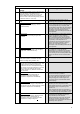
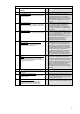
Remarks of Siemens
This section outlines how Siemens interprets the functions and processing functions according
to EN 15232-1:2017.
5) By switching stages the speed n of the fans and with that the air flow V
will be changed. With that
the power consumption of the fans changes too. For that, the following proportional (or affinity)
laws apply:
n
1
n
2
=
V
1
V
2
und
P
1
P
2
=
V
1
V
2
3
resp.
P
1
P
2
=
n
1
n
2
3
Example:
At half the speed, the air flow is reduced to its half (1/2) * also and the power consumption goes
down to an eighth (1/8) *.
Note:
* This applies under ideal (loss-free) conditions only. For practical purposes the fan vendor’s documentation should be
consulted. The reduction of the power consumption e.g. at half the air flow is substantial based on experience and
disproportionately high (e.g. 60 %)
6) This type of control is widely used. It provides for adjusting the air flow to the demand of the
rooms. However there is no direct connection between the controllers in the room and the air flow
control at the air handling unit. Changes from the rooms will be transmitted via the duct work and
will affect the air pressure (e.g. VAV-controllers close à pressure at the sensor increases). The
pressure control can react to that and adjust the air flow at the fan based on that e.g. with a
variable speed drive (VSD). Based on experience the set point for the supplied air pressure is
often set too high (be on the safe side, poorly balanced air duct work). This leads to continuously
and disproportionally high energy consumption for the air transportation (see proportional laws
under 2).
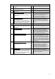
7) This control approach requires individual control of the air flow at room level based on
temperature and/or air quality (4.2, 2 and 4.4, 3). This functionality can be easily implemented in
the Siemens Desigo building automation system using the standard solution “AirOptiControl”.
Applying this solution required communicating room- and VAV-controller that provide the
necessary demand information.
8) When cooling the extract air for heat recovery purposes the humidity contained in the air can
condensate. At low temperatures this condensate can freeze at the heat exchanger surface.
Because of this the free cross-section for the air flow through the heat exchanger can be partially
or completely closed off.
Fans with variable speed drives (VSD) react to an increasing resistance at the heat exchanger
with increasing the fan speed in order to still provide the required air flow. This leads to increased
power consumption.
If fans with constant speed are used, then, with the increasing resistance, the air flow on the
extract side of the heat exchanger will be reduced in case of icing. With the power consumption
remaining about the same, an undesirable over-pressure situation in the ventilation system
occurs. This should be avoided.
Not all heat recovery constructions are similarly prone to icing. With rotating heat exchangers this
risk occurs only at very low outside air temperatures. For details on this the manufacturer’s
documentation should be consulted.
9) This protection function reduces the capacity of the heat recovery system (e.g. via bypass
damper for plate exchangers, diverting valve in a CVS-System). The reduced capacity must be
compensated with the following air heating coil in the air handling unit.