
User Manual


57
AUTOMATISCHE REGELUNG
4 VENTILATION AND AIR CONDITIONING
CONTROL
BT Grund der Energieeinsparung
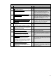
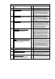
4.5 Air flow or pressure control at the air handler level
0
No automatic control:
Continuously supplies of air flow for a maximum
load of all rooms.
When the air handling unit is in operation,
always the maximally required air flow will be
conditioned and transported. This leads to a
correspondingly high energy consumption for
conditioning and transporation. The air handling
unit can also be in operation even if it is not
required.
1
On off time control:
Continuously supplies of air flow for a maximum
load of all rooms during nominal occupancy time.
The air handling unit will be operated during
nominal occupancy times and always the
maximum air flow will be conditioned and
transported which leads to a correspondingly
high energy consumption for conditioning and
transportation.
2
Multi-stage control:
To reduce the auxiliary energy demand of the fan
5
As in 1), but with the air flow adjusted in stages
(e.g. time schedule reduces the operating stage
over lunch, in late afternoon, …). Operating the
fan on a reduced stage will lead to
correspondingly reduced power consumption for
conditioning and disproportionately high
reduction of power consumption for
transportation (see proportional laws).
3
Automatic flow or pressure control without
pressure reset:
Load dependent supplies of air flow for the
demand of all connected rooms.
6
As in 1), but in addition the supply pressure will
be controlled to a fixed setpoint by modulating
the fan speed. If the air flow situation in the
rooms change, the pressure in the duct work
and the pressure control react to it and the air
flow will be adjusted accordingly. This leads to a
reduction of the energy consumption for
conditioning and transportation. The pressure
setpoint will be set accordingly to the most
critical situation which leads to an unnecessary
high supply pressure at part load operation.
4
Automatic flow or pressure control with pressure
reset:
Load dependent supplies of air flow for the
demand of all connected rooms (for variable air
volume systems with VFD).
7
As in 3), but in addition the supply pressure
setpoint will be adjusted based on demand.
With that for all supplied rooms it is ensured, that
only as much air as required will be conditioned
and will be delivered with the minimally required
pessure. By gathering the demands, the room
with the currently highest demand will be
satisfied at all times. This reduces the energy
consumption for conditioning and transportation
maximally.
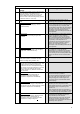
4.6 Heat recovery control (icing protection) 8
This control function is to avoid icing of the heat
exchanger.
0
Without icing protection control:
There is no specific action to avoid icing of the
heat exchanger.
As soon as exhaust air humidity ices up in the
heat exchanger (the air spaces fill with ice), the
power of the exhaust air fan must be increased
to ensure air flow in the room.
1
With icing protection control:
A control loop enables to warranty that the
exhaust air temperature leaving the heat
exchanger is not too low to avoid frosting.
9
The power of the exhaust air fan need not be
increased with icing protection limitation control.