
User Manual


61
AUTOMATIC CONTROL
4 VENTILATION AND AIR CONDITIONING
CONTROL
BT Reason for energy savings
4.9 Supply air temperature control at the AHU level
There might be several supply air temperatures
in an air conditioning system: the supply air
temperature at the outlet of the AHU, the supply
air temperature at the outlet of central re-heaters
as well as supply air temperature at the room
level (terminal re-heat boxes). This control
function is about how to determine the supply air
temperature setpoint (in case there is one) at the
air handler level not how to control the
temperature (e.g. control of heat emission at the
water-to–air HX).
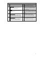
0
No automatic control
No control loop enables to act on the supply air
temperature.
The supply air temperature is provided
continuously depending on the maximum load.
The highest supply air output is continuously
delivered to the rooms or provided for re-
treatment, resulting in unnecessary energy
losses under part load conditions.
1
Constant set point
A control loop enables to control the supply air
temperature, The set point is constant and can
only be modified by a manual action.
The supply air temperature is set manually. The
air is supplied to the rooms or provided for re-
treatment. Temperature is increased manually
as needed, but then often not reduced to correct
levels. Behavior is suboptimum.
2
Variable set point with outdoor temperature
compensation
A control loop enables to control the supply air
temperature. The set point is a simple function of
the outdoor temperature (e.g. linear function).
Supply air temperature is controlled depending
on the outside temperature (corresponding to
the probable demand of the individual rooms).
Individual load of all individual rooms is not,
however, considered. As a result, there is no
way to influence how many individual room
temperature controllers reheat in the summer or
recool in the winter.
3
Variable set point with load dependent
compensation
A control loop enables to control the supply air
temperature. The set point is defined as a
function of the loads in the room. This can
normally only be achieved with an integrated
control system enabling to collect the
temperatures or actuator position in the different
rooms.
Single room plant with cascading control:
Supply air temperature is controlled depending
on the load in the single room plant or reference
room plant.
Multi-room plant with room automation:
The supply air temperature is controlled
depending on the largest individual load of all
individual rooms.
This reduces the number of individual room
temperature controllers that reheat in the
summer or recool in the winter.
Notes on both solutions:
· Energy demand placed on the HVAC plant
drops as the load decreases
· The more apart the setpoints of all room
controllers for heating and cooling (large
neutral zones), the smaller the energy
demand placed on the HVAC plant