
Specifications
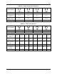

SD74
14
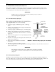
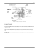
4. Place range spring assembly on actuator shaft.
5. Attach the range spring link to the input diaphragm assembly stem (See Figure 4-1).
6. Align the split clamp so that its slot is 90° from the slot in the range spring assembly. Tighten slightly.
7. Position the traveling washer on the span adjustment screw in its approximate center.
8. Calibrate the Model 74. Refer to Section 3 Calibration.
9. Lock the split clamp in place by tightening the clamp screw. Torque to 15-20 in lbs.
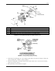
FIGURE 2-5 Mounting Plate
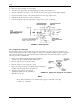
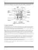
2.5.3 Suppression Spring Kit
For split ranging and for a range that starts at a pressure greater than 3 psig, add a suppression spring kit to the
Model 74 range spring kit. Table 1-3 lists available zero suppression spring kits. Install the suppression spring kit
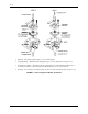
before attaching the range spring to the input diaphragm assembly. Refer to the Parts List, Figure 2-6, and the
following procedure to install the kit.
1. Remove the grommet and baffle from the input diaphragm
assembly stem. The grommet and baffle will slide off.
2. Place the suppression spring on the housing.
3. Place the spring seat on the suppression spring.
4. Depress the spring and spring seat, aligning the input diaphragm
assembly stem through the hole in the spring seat.
5. Attach the range spring hook to the input
diaphragm assembly stem. No adjustment or
calibration is necessary.
NOTE
The grommet and baffle are not re-installed with a suppression kit. They can be kept
for future use or discarded.
FIGURE 2-6 Suppression Spring Kit - Assembled