
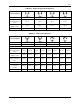
Specifications

SD74
15
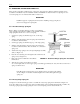
3.0 CALIBRATION
3.1 VALVE POSITIONER
The Model 74, when used as a valve positioner, has three calibration adjustments: Zero, span and output pressure
level. Make all adjustments with the positioner mounted on the actuator.
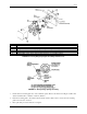
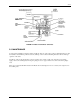
3.1.1 Rectilinear Range Spring
ZERO AND SPAN (See Figure 2-2)
1. Turn on supply air.
2. Set input signal at its minimum range pressure (3 psig for a 3 to 15 psig range).
3. Loosen the range spring seats and turn the zero screw until the take-off arm just starts to move from its
minimum stroke position.
4. Set input signal at its maximum range pressure (15 psig for a 3 to 15 psig range).
5. Turn the spring seats at the same time to reduce or increase the number of active coils of the spring. Turn the
seats until the take-off arm just starts to move from its maximum stroke position.
6. Repeat steps 2 through 5 until the desired stroke is attained.
7. Lock the zero screw by holding the lower spring seat and turning the upper spring seat clockwise
approximately 3/4".
8. Go to Section 3.2 Output Pressure Level Adjustment.
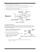
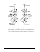
3.1.2 Rotary Range Spring
ZERO AND SPAN (See Figure 2-3)
1. Turn on supply air.
2. Set input signal at its minimum range pressure (3 psig for a 3 to 15psig range).
3. Slightly loosen the split clamp screw. Using a 3/8" open-end wrench, turn the zero adjustment until the valve
actuator is at its starting point.
Check the zero by adjusting the input signal below 3 psig; slowly increase the input signal; the actuator should
start to move when the input signal crosses 3 psig.
4. Set the input signal to its maximum range pressure (9 or 15 psig).
5. Set the span adjustment screw so that the actuator shaft assumes its maximum rotation.
Check the span by adjusting the input signal above maximum range pressure; slowly decrease the input signal;
the actuator should start to move when the input signal crosses maximum range pressure.
6. Check and reset the zero adjustment if necessary.
7. Repeat steps 2-6 as necessary to obtain the desired zero and span settings.
8. Tighten split clamp screw.
9. Go to Section 3.2 Output Pressure Level Adjustment.
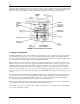
3.2 OUTPUT PRESSURE LEVEL ADJUSTMENT
The output pressure level adjustment is used to:
• Set the optimum output pressure of positioners used on valves with double-acting actuators
• Place the unused pilot plunger out of operation in positioners used on valves with single-acting actuators.