
Specifications
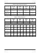

SD74
16
This section gives a procedure for each type of actuator.
Needed equipment:
1. A pressure regulator capable of providing a mid-scale input for the positioner input range.
2. Three pressure gauges: one for the input and one for each of the positioner valve connections. Additional
gauges are not required if the positioner is equipped with optional gauges.
3. A medium slotted screwdriver
Double-Acting Actuators
The output pressure level adjustment permits the pressure in the actuator chambers to be varied as desired. The
optimum actuator pressure level setting for equal speed of operation in both directions is approximately 75% of
supply pressure.
1. Make certain that there is no process force on the valve by removing or isolating the valve from the process.
2. Connect gauges to the input and valve connections, if required.
3. Turn on positioner supply.
4. Set the input (instrument) signal at mid-scale, e.g. 9 psig for a 3 to 15 psig input range. Allow actuator
pressures to stabilize.
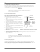
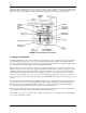
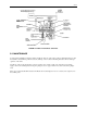
5. Turn the output level adjustment screw (see Figure 2-1) to obtain a reading approximately 75% of supply
pressure.
After making this adjustment, allow sufficient time for the pressure to stabilize. Identical valve gauge readings
should not be expected since the areas on the two sides of a piston or diaphragm may be somewhat different, due to
the stem, thus requiring a slightly higher pressure to balance an opposing force.
Single-Acting Actuators
A positioner used on single-acting actuator has one valve connection plugged, thus one plunger is not used. The
output pressure level adjustment is made to place the unused plunger out of operation.
1. Connect gauges to the input and valve connections, if required.
2. Turn on positioner supply.
3. Set the input (instrument) signal at mid-scale, e.g., 9 psig for a 3 to 15 psig input range.
4. Turn the output level adjustment screw clockwise (approximately two turns) until the pressure in the unused
valve port falls to 0 psig).
3.3 MOTION TRANSMITTER
The Model 74S Motion Transmitter has zero and span adjustments. The output pressure level adjustment is not
used.
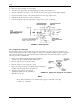
Rectilinear Range Spring
ZERO AND SPAN (See Figures 2-1 and 4-2)
1. Connect the VALVE 1 (output) port to a test gauge or mercury manometer.
2. Turn the output pressure level adjustment screw clockwise until seated.
3. Plug the VALVE 2 port with 1/4" NPT pipe plug.
4. Turn on 20 psig supply air.
5. Position the valve to its minimum stroke position.