
Specifications
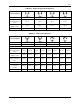

SD74
17
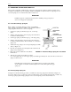
6. Loosen the spring seats and adjust the zero screw for a 3 psig output.
7. Position the valve to its maximum stroke position.
8. Turn both spring seats at the same time to increase or decrease the number of active coils, for a 15 psig output.
9. Repeat steps 5 through 8 until the transmitter is calibrated.
10. Lock the zero screw by holding the lower spring seat and turning the upper spring seat clockwise
approximately 3/4".
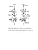
Rotary Range Spring
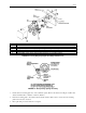
ZERO AND SPAN (Figures 2-1 and 2-3)
1. Connect the VALVE 1 (output) port to a test gauge or mercury manometer.
2. Turn the output pressure level adjustment screw clockwise until seated.
3. Plug the VALVE 2 port with a 1/4" NPT pipe plug.
4. Turn on supply air.
5. Position the valve to its minimum stroke position.
6. Slightly loosen the split clamp; use a 3/8" open-end wrench to turn the zero adjustment for a 3 psig output.
7. Position the valve to its maximum stroke position.
8. Turn the span adjustment screw for a 15 psig output.
9. Repeat steps 5 through 8 until the transmitter is calibrated.
10. Tighten split clamp screw.
4.0 OPERATION
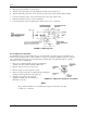
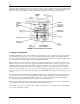
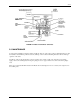
4.1 VALVE POSITIONER
The positioner operates on a force-balance principle. The forces are: range spring tension and the pressure level of
the instrument signal. The two forces oppose each other at the input diaphragm assembly. The positioner will move
the valve until the tension of the range spring equals the force of the control instrument signal at the input
diaphragm assembly.
Figure 4-1 shows the positioner connected to a double-acting piston operator. Here a balanced condition exists with
the valve at mid-position. When the instrument signal pressure is increased, the resultant force on the input
diaphragm assembly exceeds the tension on the range spring and the assembly moves up. The upward movement
increases the clearance between the beam and detector nozzle, causing a decrease of pressure in the nozzle circuit.
The decreasing pressure unbalances the forces across the lower diaphragm of the pilot valve actuator rod assembly
and causes the assembly to move down. The downward movement pushes the PLUNGER 2 off its supply seat
increasing the VALVE 2 pressure. At the same time, PLUNGER 1's exhaust seat, which is part of the pilot valve
actuator rod assembly, moves away from the plunger. VALVE 1 pressure thus decreases as the air is exhausted to
atmosphere.
The resultant pressure differential across the valve actuator piston moves the piston downward and thereby
increases the range spring tension. As a force-balance condition is approached, VALVE 1 and VALVE 2 pressures
begin to equalize. At balance, the pilot valve actuator rod assembly has moved back to the neutral position where
the plungers are neither supplying air to, nor exhausting air from, the piston operator.
A decrease of the instrument signal pressure reverses all of the foregoing actions and results in an upward
movement of the actuator piston and valve stem.