
Specifications
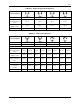

SD74
18
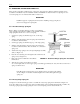
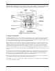
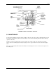
On spring-loaded and cushion-loaded operators, only one of the positioner outputs is used; the other is plugged. The
Model 74 is then a single-acting positioner, working against the operator spring force or cushion load. The previous
principle of operation describing the double-acting positioner applies also to the single-acting positioner.
FIGURE 4-1 Valve Positioner Schematic
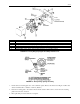
4.2 MOTION TRANSMITTER
The Motion Transmitter works on the force-balance principle. The forces are comprised of range spring tension and
the feedback signal pressure. These oppose each other at the input diaphragm assembly. The transmitter will vary
the output, which feeds back through a restriction to the input diaphragm assembly. The resultant force balances the
force exerted by the range spring tension at the input diaphragm assembly.
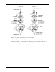
Figure 4-2 shows the motion transmitter connected to an input motion linkage arm. A downward movement of the
linkage arm increases tension on the range spring. The resultant downward force exceeds the opposing force of the
feedback signal on the input diaphragm assembly, causing the assembly to move down. This movement decreases
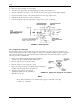
the clearance between the beam and detector nozzle and causes an increase of pressure in the nozzle circuit. The
increase of pressure unbalances the forces across the lower diaphragm of the pilot valve actuator rod assembly and
causes the assembly to move upward. This movement pushes PLUNGER 1 off its supply seat, increasing the output
pressure.
The output pressure is fed back through the stabilizing restriction into the input diaphragm assembly. This pressure
increases until it exerts a force on the input diaphragm assembly equal to that applied by the range spring tension.
When in balance, the input diaphragm assembly has moved to a neutral position. The actuator rod assembly has
closed the pilot supply, thus maintaining the feedback pressure at the balance level.
When the motion arm moves upward, spring tension decreases and the foregoing actions are reversed. The actuator
rod assembly will exhaust the output pressure until it reaches the balance level.
The VALVE 1 port is the only one used in the transmitter. The VALVE 2 port is plugged; therefore, PLUNGER 2
has no effect on transmitter operation.