
Specifications


SD74
22
5.2 ASSEMBLY
To assemble, reverse the disassembly procedure and take into account the following:
1. Exercise care when installing the output diaphragm assembly. Carefully guide the capillary tube into the small
hole in the upper housing. Be certain the capillary is engaged in the hole before installing and tightening the
clamping plate.
2. When assembling the diaphragm spacer to the input diaphragm assembly, align the small hole in the lower
diaphragm (beam side of the assembly) to the hole in the spacer. The small hole in the upper diaphragm (range
spring side of the assembly) does not line up with a hole.
3. Lubricate the two O-rings on the input diaphragm assembly. Slide the assembly into the upper housing so that
the small hole in the lower diaphragm and spacer line up with the small hole in the upper housing.
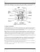
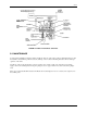
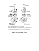
4. Install the beam after the input and output diaphragm assemblies have been installed and securely tightened.
Torque the two screws that hold the beam to the Output Diaphragm Assembly to 2.0-2.5 in. lbs. Set the height
of the beam, per Figure 5-3, before locking the small jam nuts on the input diaphragm assembly (the 3/32"
dimension is a starting point and may have to be adjusted up or down if calibration cannot be achieved).
5. A complete calibration is required after assembly. This includes zero, span and output pressure level
adjustments.
FIGURE 5-3 Diaphragm and Beam Assembly
5.3 PREVENTIVE
Most problems associated with pneumatic instruments can be avoided by the use of clean, dry, oil-free instrument
air. Refer to Section 2.2 Instrument Air Requirements in this manual and to the Instrument Society of America’s
publication “Quality Standard for Instrument Air” (ISA-S7.3).
!