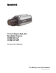
/3 inch Super High-Res Day-Night Camera CCBS1337-LP CCBS1337-MP Instruction Manual Fire Safety & Security Products Siemens Building Technologies
Data and design subject to change without notice. / Supply subject to availability. © 2005 Copyright by Siemens Building Technologies AG We reserve all rights in this document and in the subject thereof.
Contents 1 1.1 1.2 1.3 General Information ................................................................................5 General Safety Precautions ......................................................................5 Electromagnetic Compatibility (EMC) .......................................................5 Manufacturer's Declaration of Conformity.................................................6 2 Ordering Data .....................................................................................
7.2.16 7.2.17 7.2.18 7.2.19 NEXT/ BACK ...........................................................................................24 EXIT ........................................................................................................24 CANCEL..................................................................................................24 DEFAULT ................................................................................................24 8 Index ..........................................
General Information 1 General Information 1.1 General Safety Precautions Read these instructions carefully before connecting the camera in order to avoid damage caused by improper installation or use. Installation may be done only by authorized personnel according to the local safety regulations. Operate the camera only with the designated voltage. Follow the safety instructions for the camera. Never use the camera for purposes other than those designated.
Ordering Data 1.3 Manufacturer's Declaration of Conformity EU Directive The following applies to the equipment described in this instruction manual: The product fulfils the requirements of EU directive 89/336/EEC with regard to “electromagnetic compatibility“ and EU directive 73/23/EEC, the ”low-voltage directive“, according to EN 60065.
General Guidelines 4 General Guidelines 4.1 Operation & Storage Avoid filming very bright objects (such as lighting fixtures) for an extended period. Do not operate or store the unit in the following locations: – Extremely hot or cold places. – Close to sources of strong magnetic fields. – Close to sources of powerful electromagnetic radiation, such as radio or TV transmitters. – In humid or excessively dusty places. – Where exposed to mechanical vibrations.
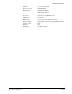
Technical Specifications Technical Specifications 5.1 Dimensions 63 5 72 5.2 122 Product Specifications Image area 4.9 x 3.7 mm Pickup elements 752 (H) x 582 (V) pixels 1/3” ExView CCD Scanning System 2:1interlace PAL V: 50 Hz, H: 15.625 Hz Sync system Internal/ line lock selectable (AC only) Video output BNC composite, Y/C output Lens mount CS mount Resolution 520 TV lines (Horizontal) @ Y/C output Gamma correction 0.45, 1 Minimum illumination CL: 0.4 lux @F=1.
Technical Specifications D/N level HIGH, MID, LOW D/N DLY 0, 5, 10, 15, 20 selectable Aperture correction HIGH, MID, LOW White balance ATW1:2600°K~6000°K ATW2: 2500°K~10,000°K Manual: 32 steps by push button for R and B Iris control Video / DC iris for galvanometer lens Camera text 16 characters OSD control 5 control keys on the side panel of camera Default settings Default setting restored by pushing the DEFAULT button Remote control RS-485 Alarm IN 1CH Alarm OUT NC or NO selectable 9
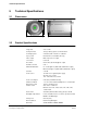
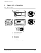
Camera Parts & Connections 6 Camera Parts & Connections 6.1 Camera Parts 1. Back focus adjustment ring ① 2. Back focus lock screw ② 3. Tripod mount hole ③ 4. IRIS connector ④ 5. Power indicator ⑤ 6. Video output ⑥ 7. Power cord (or power terminal) ⑦ 10 Siemens Building Technologies Fire Safety & Security Products 03.
Camera Parts & Connections 8. 9. External control terminal: (From right to left) Pin Pin Definition Description 1 Data + RS485 signal 2 Data – 3 Alarm IN 4 GND If the alarm IN & GND are shorted, the alarm function will be active. (Please set ALARM FUNC to ON in OSD menu.) 5 Alarm OUT Alarm output circuit. 6 COM 7 B/W 8 C/L 9 GND If D/N MODE set in manual mode, this function will be enabled. If B/W & GND are shorted, the video signal is monochrome.
Camera Parts & Connections 6.3 OSD Setting Hierarchy OSD SETTING D/N MODE AUTO MONO D/N LEVEL HIGH LOW D/N DELAY 0 5 ALC ELC EXPOSURE LENS TYPE MENU SHUTTER GAIN SYNC BLC 1/50 NORMAL COLOR MANUAL MID 10 15 20 LENS LEVEL 1/120 1/250 1/500 1/1K 1/100K 1/10K 1/4K 1/2K TURBO OFF INT LL OFF BLC1 BLC2 BLC3 BLC4 BLC6 BLC5 (P1) WHITE BAL GAMMA APERTURE ATW1 0.
Installing the Camera 7 Installing the Camera 7.1 Installation 1. Connect the BNC cable to the video output ⑥ 2. Connect the power source to the power terminal Caution: If using a DC supply, make sure the polarity is correct. Incorrect connection may cause malfunction and/or damage to the camera. 3. To reduce radiation sufficiently, please wind one turn around the core, see figure below Location Core illustration for what camera Power cable LP Y/C cable LP / MP EIM-0050751G 4.
Installing the Camera 7.2.1 D/N MODE D/N MODE AUTO D/N LEVEL HIGH D/N DELAY 15 sec EXPOSURE SHUTTER 1/50 GAIN NORMAL SYNC LL:000 BLC OFF NEXT EXIT CANCEL DEFAULT Fig. 1 D/N MODE This function sets the Day/Night mode to automatic, color, B/W or external control of setting to B/W or color. Move the cursor to the position shown in Fig. 1. Use the LEFT/ RIGHT button to select AUTO, MONO, COLOR or MANUAL mode.
Installing the Camera 7.2.2 D/N LEVEL D/N MODE AUTO D/N LEVEL HIGH D/N DELAY 15 sec EXPOSURE SHUTTER 1/50 GAIN NORMAL SYNC LL:000 BLC OFF NEXT EXIT CANCEL DEFAULT Fig. 2 D/N LEVEL This function sets the filter switchover point to high, low or medium. Configure a switchover point from COLOR mode to B/W mode. Move the cursor to the position shown in Fig. 2. Use the LEFT/ RIGHT button to select HIGH, LOW or MID. This setting is only relevant if the D/N mode is set to AUTO. 7.2.
Installing the Camera 7.2.4 EXPOSURE D/N MODE AUTO D/N LEVEL HIGH D/N DELAY 15 sec EXPOSURE SHUTTER 1/50 GAIN NORMAL SYNC LL:000 BLC OFF NEXT EXIT CANCEL DEFAULT Fig. 4 EXPOSURE This function sets ALC for Auto IRIS lens control or ELC for auto electronic shutter. Move the cursor to the position shown in Fig. 4. The exposure level can be adjusted by moving the LEVEL cursor on the menu accordingly. ALC: ALC MENU LENS TYPE DC LENS LEVEL ----------*----BACK ELC: Auto electronic shutter mode.
Installing the Camera 7.2.6 GAIN D/N MODE AUTO D/N LEVEL HIGH D/N DELAY 15 sec EXPOSURE SHUTTER 1/50 GAIN NORMAL SYNC LL:000 BLC OFF NEXT EXIT CANCEL DEFAULT Fig. 6 GAIN Selection of GAIN: (NORMAL / TURBO / OFF) Move the cursor to the position shown in Fig. 6. Using the LEFT/ RIGHT button, set the gain to NORMAL, TURBO or OFF. 7.2.7 NORMAL Standard position, GAIN=24dB. TURBO High-sensitivity position, GAIN = 30dB. OFF Minimum gain. If this is selected, D/N mode (AUTO) is disabled.
Installing the Camera 7.2.8 BLC D/N MODE AUTO D/N LEVEL HIGH D/N DELAY 15 sec EXPOSURE SHUTTER 1/50 GAIN NORMAL SYNC LL:000 BLC OFF NEXT EXIT CANCEL DEFAULT Fig. 8 BLC This function is for selecting the backlight mode (OFF, BLC1, BLC2, BLC3, BLC4, BLC5, BLC6) Move the cursor to the position shown in Fig. 8. Using the LEFT/ RIGHT button to choose OFF, BLC1, BLC2, BLC3, BLC4, BLC5 or BLC6. OFF The BLC function is off.
Installing the Camera Move the cursor to the position shown in Fig. 9. Use the LEFT/ RIGHT button to choose between ATW1, ATW2, and manual mode. ATW1 The TTL auto trace white balance algorithm is designed for perfect color reproduction. The color temperature range is 2600°K-6000°K. ATW2 The TTL auto trace white balance algorithm is designed for perfect color reproduction. The color temperature range is 2500°K-10000°K. Manual mode Press the ENTER button to enter manual mode.
Installing the Camera 7.2.12 MIRROR WHITE BAL ATW2 GAMMA 0.45 APERTURE MID MIRROR OFF PRIVACY ZONE OPTION REMODE BACK EXIT CANCEL DEFAULT Fig. 12 Mirror function Move the cursor to the position shown in Fig. 12 Use the LEFT/ RIGHT button to choose ON or OFF. 7.2.13 PRIVACY ZONE WHITE BAL ATW2 GAMMA 0.45 APERTURE MID MIRROR OFF PRIVACY ZONE OPTION REMODE BACK EXIT CANCEL DEFAULT Fig.
Installing the Camera 7.2.14 OPTION WHITE BAL ATW2 GAMMA 0.45 APERTURE MID MIRROR OFF PRIVACY ZONE OPTION REMOTE BACK EXIT CANCEL DEFAULT Fig. 14 OPTION Select blemish compensation, back focus adjustment, alarm ON/OFF, alarm output, alarm delay, alarm text, chroma & camera text. Move the cursor to the position shown in Fig. 14. Use the LEFT/ RIGHT button to select BLEMISH compensation, BACKFOCUS adjust mode and alarm settings. 7.2.14.
Installing the Camera OFF The alarm input function on the rear panel is disabled. ON The alarm input function on the rear panel is enabled. When an alarm occurs, the status of alarm output will change, i.e. from NO to NC or from NC to NO, depending on the setting of ALARM OUT. Use the OSD navigation keys to define the optional alarm text to be displayed in case of an alarm. 7.2.14.4 ALARM OUT This function sets the initial status of the ALARM output relay. NO: normally open NC: normally closed 7.2.
Installing the Camera 7.2.15 REMOTE WHITE BAL ATW2 GAMMA 0.45 APERTURE MID MIRROR OFF PRIVACY ZONE OPTION REMOTE BACK EXIT CANCEL DEFAULT Fig. 18 REMOTE This function is for setting the remote control menu Move the cursor to the position as shown in Fig. 18. Use the ENTER button to enter the submenu. REMOTE MENU MODEL CCBS1337-LP ADDRESS 001 ~ 099 BAUD RATE 2400 PROTOCOL SIEMENS-U SOFT VER. X.2.2 PATTERN OFF SAVE DEFAULT 7.2.15.1 MODEL MODEL indicates the camera model. 7.2.15.
Installing the Camera 7.2.15.4 PROTOCOL Select one of the 3 various protocols, depending on the type of remote connectivity, for remote OSD control camera setup: SIEMENS-B: When using the camera with bi-directional remote control under remote software and PC (remote software provides full parameter setup). SIEMENS-U: When using the camera for unidirectional communication with SIMATRIX via converter CAC0103 (V1.6).
Index 8 Index A N aperture, 18 NEXT/ BACK, 23 B O BLC, 17 operation and storage, 7 OPTION, 20 ordering data, 6 OSD settings, 12 C camera parts, 10 CANCEL, 23 CCD Characteristics, 7 cleaning, 7 D D/N delay, 14 D/N level, 14 D/N MODE, 13 DEFAULT, 23 dimensions, 8 E EU Directive, 6 EXIT, 23 exposure, 15 P package contents, 6 pin assignments, 11 privacy zone, 19 product specifications, 8 R REMOTE, 22 S safety precautions, 5 shutter, 15 SYNC, 16 synchronization, 16 F T function setting, 13 Tr
Issued by Siemens Building Technologies Fire & Security Products GmbH & Co. oHG D-76181 Karlsruhe www.sbt.siemens.com/fsp Document No. A24205-A336-B480 Edition 03.2005 © 2005 Copyright by Siemens Building Technologies AG Data and design subject to change without notice. Supply subject to availability. Printed in the Federal Republic of Germany on environment-friendly, chlorine-free paper.