Tools Gateway GW-21 Configurator User Manual Document No. Edition Supersedes e1754 02.
Cerberus Division Table of contents Table of contents 1 Introduction _________________________________ 1 1.1 1.2 1.3 1.4 The aim of this manual __________________________________________ 1 Who this manual is for __________________________________________ 1 Document structure_____________________________________________ 2 Hardware overview _____________________________________________ 2 2 User interface ________________________________ 4 2.1 2.2 2.3 2.
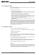
Cerberus Division Introduction 1 Introduction 1.1 The aim of this manual This manual provides all of the information and instruction necessary to use the GW21 Configurator Program. GW 21 Configurator is the software used to configure the EPROMs needed by the Gateway GW-21 to operate properly. The manual explains in detail how to set the relevant parameters for each Pad inside the gateway, how to configure the interactions among subsystems and how to set the reaction programs.
Cerberus Division Introduction 1.3 Document structure This manual provides the information and procedures necessary to successfully configure the Gateway EPROMs. It is structured in the following way: • Chapter 1 is the chapter you are currently reading and it supplies an overview of manual and software performances. • Chapter 2 deals with the user interface, i.e. keyboard and screen layout, option selection, software startup, help screens and access levels.
Cerberus Division Introduction GW-21.04 This configuration has 4 serial lines; it is composed by the CPU board that has onboard 4 communication lines. Up to three control panels can be connected to one workstation, or it can connect two workstations and two subsystems. e1754.doc Data and design subject to change without notice. Supply subject to availability © Copyright by Siemens Building Technologies AG Cerberus Division, CH-8708 Männedorf, Switzerland 1999 02.
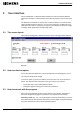
Cerberus Division User interface 2 User interface GW-21 Configurator is a Windows based software and it shares with the Windows environment a number of characteristics that makes the program easy to learn and to use. The Windows environment for instance has a common interface to access functions, shortly described below for reference.
Cerberus Division User interface This is a data entry field where you can type text Fig. 2-2 Option buttons (Fig. 2-3) An option button represents the activation/de-activation of a single choice or of a set of choices. Option buttons are represented by squares. When an option button is selected, the square is filled by a check mark. When the choice is not selected, the box is empty. This option box lets you select the number of lines to be used, i.e. between GW21-06 or GW21.04 Fig.
Cerberus Division User interface The drop down list shows usually only one value. When you click the downpointing arrow a list of possible options opens. Fig. 2-4 Sometimes the controls or the menu options could appear dim: this means that they are not enabled. This happens usually when a related check box or menu option was previously selected, disabling the control.
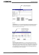
Cerberus Division Configuration 3 Configuration To configure the lines in the GW-21, you just have to follow the steps described below: 1. define the GW-21 model you are using. GW-21.04 has four lines (the default), GW-21.06 has 6 lines. Should you be using the GW-21.04, the two rightmost controls on the page are not used. This option box lets you select the number of lines to be used, i.e. between GW21-06 or GW21.04 Fig. 3-1 2.
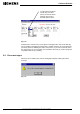
Cerberus Division Configuration The drop down list presents all the subsystems currently available Fig. 3-3 If you choose LOOP on a line, a field appears that let you key in the MK7022 address that acts as an interface toward the loop. 3.1 How to create a new configuration From the File menu, select New. The data currently configured will be cleared and a new configuration will be started. 3.2 How to save the current configuration From the file menu, select Save. A file dialog box will be shown.
Cerberus Division Configuration 3.4 The About dialog box You can display the current version of the software you are using clicking on the About menu option. A dialog box that looks like the following is displayed: Fig. 3-5 e1754.doc Data and design subject to change without notice. Supply subject to availability © Copyright by Siemens Building Technologies AG Cerberus Division, CH-8708 Männedorf, Switzerland 1999 02.
Cerberus Division Interactions 4 Interactions GW-21 Configurator lets you define the interaction among subsystem. You can program the gateway in order to send a message to a subsystem when it receives a specific message from another subsystem. 4.1 The reaction message The reaction message is triggered by the source message, and it is linked to it through the reaction program number. The figure that follows shows the configuration dialog box for the reaction message. Fig.
Cerberus Division Interactions 4.2 The source message Fig. 4-2 The meaning of fields in the previous picture is as follows: 4.3 Description this is the text that describes the interaction on the source message side. It could be for instance "Fire alarm Zone 1 Building 10" Subsystem this the Line number (as defined on the Line dialog box) on the GW21 connected to the subsystem for which you wish to define the interaction. Len (Dec) is the number of byte in the source message .
Cerberus Division Interactions On a Line you can configure up to four interactions, one for each line. The interactions you configure can deal with other lines of the same Pad, or one or more lines on a different Pad, or more lines on different Pads. To know what you need to insert here in the Data field both of Source and Reactions, you can monitor the messages exchanged on the network using the Line Monitor on LMS that shows the messages generated on the field and the commands issued by the operator.
Cerberus Division Make file ABS 5 Make file ABS In order to generate the ABS file that could be downloaded to the EPROM, you should : • save the CNF file created with the GW-21 Configuration program • run the GW21_CNF program. This is a DOS program described in the following section of this manual • create the EPROM using the ABS file generated by the GW21_CNF program 5.1 How to use the GW21_CNF program From the main menu you must choose first the "Make Eprom" option.
Cerberus Division Make file ABS You can use the ABS file with an EPROM programmer to generate the EPROM to be installed in the Gateway. Please refer to ANNEX A - EPROMs supported section for a detail about the EPROM chips to be used. You can alternatively generate and download the file to the Gateway using the SLTA (LonWORKS) connection. To do so, access the option 2 of the main menu, labeled "Download".
Cerberus Division Glossary 6 Glossary CMS Pad This pad is in charge to manage communication to and from the CMS/LMS supervising system. Usually there is only one CMS Pad in a gw-20, but in redundant configuration up to two can be provided. CMSDL It is the protocol used to communicate between gateway and CMS/LMS supervising system. Initiating message A message that starts up a reaction program. It is a telegram sent to the supervising system by one of the subsystem.
Cerberus Division ANNEX A - EPROMs supported 7 ANNEX A - EPROMs supported The gateway GW-21 can use only EPROMs of the following type: • AM 29F010-12OPC 128 KB with access time < 120 ns The absolute file format is MOTOROLA. The EPROM programmer to be used is any type able to download in the above mentioned EPROM type an ASCII file. Please refer to the EPROM programmer documentation for details about connection between it and the PC, software installation and file downloading.
Cerberus Division ANNEX B - Subsystems messages 8 ANNEX B - Subsystems messages This annex lists for each subsystem the messages it can generate (Initiating messages) as well as the commands it can receive from the gateway. To know the hexadecimal code you need to insert in the Data field both for Source and Reactions, you can monitor the messages exchanged on the network using the Line Monitor on LMS that shows the messages generated on the field and the commands issued by the operator.
Cerberus Division ANNEX B - Subsystems messages 8.1 Initiating messages 8.1.
Cerberus Division ANNEX B - Subsystems messages Description Message (in hexadecimal) DIGITAL INPUT ... ON FF 0L LL E1 ii 41 4F DIGITAL INPUT ... OFF FF 0L LL E1 ii 41 3C DETECTOR ACTIVE (line-element) FF 0L LL LL ee 67 4F DETECTOR INACTIVE (line-element) FF 0L LL LL ee 67 3C LLL=local address gg=group ee=element ii=input 8.1.
Cerberus Division ANNEX B - Subsystems messages Description Message (in hexadecimal) PANEL PROTECTION ON 53 4L LL 00 D4 58 55 PANEL PROTECTION OFF 53 4L LL 00 D4 58 56 PANEL PROTECTION ERRONEOUSLY OFF 53 2L LL 00 D4 58 66 CODE ALARM 53 2L LL 00 D3 FF 55 CODE ALARM ACK 53 3L LL 00 D3 FF 55 CODE ALARM RESET 53 4L LL 00 D3 FF 85 DETECTOR ADDRESS ... NORMAL 53 4L LL gg ee 69 3C DETECTOR ADDRESS ... OUT 53 4L LL gg ee 69 5E DETECTOR ADDRESS ..
Cerberus Division ANNEX B - Subsystems messages 8.1.3 CC40/CF9020/40 family Description e1754.doc Message (in hexadecimal) GENERAL ALARM 53 2i ii ADF 01 00 GENERAL ALARM ACK. 53 3i ii ADF 01 00 GENERAL ALARM RESET 53 4i ii ADF 01 00 INTRUSION ALARM 53 2i ii ADF 01 05 INTRUSIN ALARM ACK. 53 3i ii ADF 01 05 INTRUSIN ALARM RESET 53 4i ii ADF 01 05 HOLD-UP ALARM 53 2i ii ADF 01 06 HOLD-UP ALARM ACK.
Cerberus Division ANNEX B - Subsystems messages Description Message (in hexadecimal) EXTERNAL HORN OFF 53 4i ii 00 E5 73 4D CONTROL UNIT PROTECTION ON 53 4i ii 00 D4 58 55 CONTROL UNIT PROTECTION OFF 53 4i ii 00 D4 58 56 TIME PROGRAM ON 53 4i ii 1C tt 6B 55 TIME PROGRAM OFF 53 4i ii 1C tt 6B 56 USER LOGIN 53 4i ii 14 hh 70 6B USER LOGOUT 53 4i ii 14 hh 70 6C ANTIMASKING ZONE NORMAL 53 4i ii 18 aa 7C 3C ANTIMASKING ZONE ACTIVE 53 4i ii 18
Cerberus Division ANNEX B - Subsystems messages Description Message (in hexadecimal) DETECTION PRE ALARM ACK. 47 3i ii xx yy 04 01 DETECTION GAS ALARM RESET 47 0i ii xx yy 04 85 DETECTION GAS ALARM 47 2i ii xx yy 07 FF DETECTION GAS ALARM ACK. 47 3i ii xx yy 07 01 DETECTION ALARM RESET 47 0i ii xx yy 07 85 DETECTION RESET 47 0i ii xx yy 00 85 FAULT NORMAL 50 0i ii E1 ED 3A 3B FAULT 50 0i ii E1 ED 3A 3A FAULT ACK.
Cerberus Division ANNEX B - Subsystems messages Description 24[34] Message (in hexadecimal) EXTERNAL HORN FAULTY 57 3i ii ADF EXTERNAL HORN OFF 57 3i ii ADF 73 56 INTERNAL HORN INACTIVE 57 4i ii ADF 7A 4D INTERNAL HORN ACTIVE 57 3i ii ADF 7A 4F INTERNAL HORN FAULTY 57 3i ii ADF 7A 46 INTERNAL HORN OFF 57 3i ii ADF 7A 56 Data and design subject to change without notice.
Cerberus Division ANNEX B - Subsystems messages 8.2 Reaction programs A reaction program must always terminate with the END OF PROGRAM instruction. 8.2.1 CERBAN CZ10 In the following table, LL represents the local address and gg the group number or the digital input/output. Description e1754.
Cerberus Division ANNEX B - Subsystems messages LLL=local address gg=group 8.2.2 CERBAN CZ12/CS4 Description Message (in hexadecimal) ACKNOWLEDGE FAULTS FF 5A 1L LL 00 00 74 86 ACKNOWLEDGE ALARMS FF 53 1L LL 00 00 00 80 ACKNOWLEDGE ANOMALY STATES FF 53 1L LL 00 EC 75 89 RESET ALARMS FF 53 1L LL 00 00 00 83 SET ORGANISATION NIGHT FF 53 1L LL 00 EF 55 55 SET ORGANISATION DAY FF 53 1L LL 00 EF 55 56 SET GROUP ..
Cerberus Division ANNEX B - Subsystems messages Description Message (in hexadecimal) EXCLUDE ALL SECTION DETECTORS 53 1i ii ADF 64 69 INCLUDE ALL SECTION DETECTORS 53 1i ii ADF 64 55 TEST ALL SECTION DETECTORS 53 1i ii 64 57 CONTROL UNIT PROTECTION ON 53 1i ii 00 D4 58 55 CONTROL UNIT PROTECTION OFF 53 1i ii 00 D4 58 56 SET ORGANIZATION A NIGHT 53 1i ii 00 EF 55 55 SET ORGANIZATION A DAY 53 1i ii 00 EF 55 56 DISABLE USER PASSWORD 53 1i ii 18 hh 72
Cerberus Division ANNEX B - Subsystems messages 8.2.6 CC11 Description Message (in hexadecimal) GENERAL ALARM/LOCAL ALARM ACK 57 1i ii Aa CD FF 80 GENERAL ALARM/LOCAL ALARM RESET 57 1i ii Aa CD FF 83 ORGANIZATION AREA NIGHT 57 1i ii Aa EF 55 55 ORGANIZATION AREA DAY 57 1i ii Aa EF 55 56 EXTERNAL HORN FAULT ACK.
Cerberus Division GW-21 Configurator trouble report 9 GW-21 Configurator trouble report From : Company Name ............................................................................................................... Name................................................................................................................................ Address ........................................................................................................................... City....................
Cerberus Division Index 10 Index GW-21.