
User Manual


Cerberus Division
Introduction
2[34]
Data and design subject to change without notice. Supply subject to availability
© Copyright by CERBERUS AG, CH-8708 Männedorf, Switzerland 1995
02.99 e1754.doc
1.3 Document structure
This manual provides the information and procedures necessary to successfully con-
figure the Gateway EPROMs.
It is structured in the following way:
• Chapter 1 is the chapter you are currently reading and it supplies an overview of
manual and software performances.
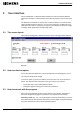
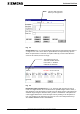
• Chapter 2 deals with the user interface, i.e. keyboard and screen layout, option
selection, software startup, help screens and access levels.
• Chapter 3 describes how to operate with the configuration files.
• Chapter 4 deals with the configuration of interactions among subsystems. In this
chapter is described how to configure both the initiating messages, that start the
interaction, and the reaction programs, that perform it.
• Chapter 5 describes how to generate the absolute file to be transmitted to the
EPROM programmer.
The following five chapters are for reference and contain these information: Chapter 6
contains the glossary, to explain the meaning of some words specific to this manual;
Chapter 7, named Annex A, lists the EPROMs to be used with the gateway. Chapter
8 (Annex B) shows the initiating messages and the messages to be used in the reac-
tion programs for the various subsystems. Chapter 9 is the form to be submitted to
Cerberus Dati in case of trouble using the software. Chapter 10 closes the document
and contains the index to the manual.
1.4 Hardware overview
The GW-21 Gateway provides the following main functions:
1. interface between subsystems and operator workstations (LMS or a foreign sys-
tem);
2. interactions among subsystems:
3. protocol conversions.
The GW-21 gateway is composed by one CPU board with serial communication ca-
pability to which can be connected an optional expansion board with additional serial
lines in a piggyback configuration.
In a two level network architecture, the GW-21 can be used as communication layer
that connect the subsystems to a higher level GW-20.
The GW-21 complies with the latest European Union standards for emission and im-
munity to electromagnetic disturbances. It is designed to replace the GW-01.
Two kinds of hardware configurations are foreseen:
GW-21.06
This configuration has 6 serial lines; it requires CPU board and an additional expan-
sion board with two more asynchronous serial lines. Using this configuration you can
connect up to four subsystems to one or two workstations. To configure this version,
you should enable explicitly a flag in the software front panel.