GW-23 Gateway GW-23 Technical Manual Document No. Edition Supersedes e1476 03.
Cerberus Division Table of contents Table of contents e1476.doc 1 Introduction _________________________________ 1 1.1 1.2 Scope of this document _________________________________________ 2 Related publications ____________________________________________ 2 2 Product description ___________________________ 3 2.1 2.2 2.
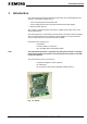
Cerberus Division Introduction 1 Introduction The GW-23 interfaces both the peripheral control units and a virtual digital I/O subsystem to a structured network such as: • X.25 via X.28 asynchronous RS-232 PAD • X.25 via ISDN channel D and asynchronous RS-232 terminal adapter • Ethernet TCP/IP protocol Also, a dial-up, switched modem connection is supported as backup of any of the above listed solution.
Cerberus Division Introduction 1.1 Scope of this document This manual is intended as a guide for planning, installation and service personnel of Cerberus danger management systems which use GW-23 device. All necessary information to install a GW-23 gateway are listed in this manual. 1.2 Related publications The following documents could be useful in dealing with GW-23 gateway and understanding how it relates to other pieces of the LMS network: LMSmodular User manual LMSmodular V2.
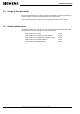
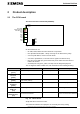
Cerberus Division Product description 2 Product description 2.1 The CPU board The CPU board is the main board (CD98600). Reset Reset LD1 Vitality LD3 Identification LD5 RAM error RX1 TX1 RX2 TX2 RX3 TX3 RX4 TX4 SW1 SW2 SW3 SW4 Fig.
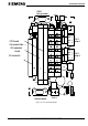
Cerberus Division Product description 2.2 The connection board The connection board (CD96812) has two connectors to insert the CPU and I/O board in. On the board there are two DB9 D connectors for the two serial ports (Com 3 and 4). COM 1 and 2 are accesible through screw connectors - only the TX, RX and GND signals are available. They are used to connect the Cerberus control panels. On the same connection board there is the power supply block.
Cerberus Division Product description COM3 Dial-up modem LON RX 1 GND 2 COM 1 GND 3 Cerban 1 TX 4 CPU board Component side → I/O expansion board RX 1 GND 2 I/O connector COM 2 GND 3 Cerban 2 TX 4 COM 4 Network adapter Power (13.8 V) Fig. 2-3 - The connection board e1476.doc Data and design subject to change without notice. Supply subject to availability © Copyright by Siemens Building Technologies AG Cerberus Division, CH-8708 Männedorf, Switzerland 1999 03.
Cerberus Division Product description 2.3 Power supervision The power supervision board is reporting the following information on a set of LEDs: 6 [14] Red ⊗ ⊗ Tamper: Yellow ⊗ Low Battery: normally OFF, it is ON if voltage drops below 10.8V± 0,5V Yellow ⊗ Fuse Battery: normally OFF, if ON, it indicates that fuse (T3.
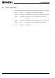
Cerberus Division connection cables 3 connection cables 3.1 Connection GW-23 - ISDN adapter TOV GW-22 Male 25 pin Male 9 pin 13 12 11 10 9 8 7 5 4 4 3 3 9 6 5 8 7 2 2 25 24 23 22 21 20 19 18 17 16 15 14 6 1 1 e1476.doc Data and design subject to change without notice. Supply subject to availability © Copyright by Siemens Building Technologies AG Cerberus Division, CH-8708 Männedorf, Switzerland 1999 03.
Cerberus Division connection cables 3.2 Connection GW-23 - Modem Modem GW-22 Male 25 pin Male 9 pin 13 12 11 10 9 8 7 5 9 6 5 4 4 8 3 3 7 2 2 25 24 23 22 21 20 19 18 17 16 15 14 6 1 1 3.3 Connection to Cerberus subsystem GW-23 COM1 / COM2 Cerberus control unit / modem T 8 [14] Rx 1 ¡ Tx Tx 4 ¡ Rx Gnd 2 ¡ Gnd Data and design subject to change without notice.
Cerberus Division connection cables 3.4 Connection layout e1476.doc Data and design subject to change without notice. Supply subject to availability © Copyright by Siemens Building Technologies AG Cerberus Division, CH-8708 Männedorf, Switzerland 1999 03.
Cerberus Division Technical data 4 Technical data Lines to supervision center 1 full-modem RS-232 line for X.25/X.