Manual LMSmodular Hardware Section 2 Cerberus® LMSmodular Cerban Splitter CBS-3 Technical Manual Cerberus Security for People and Assets Siemens Building Technologies Cerberus Division
Data and design subject to change without notice. / Supply subject to availability. © Copyright by Siemens Building Technologies AG We reserve all rights in this document and in the subject thereof.
1 1.1 1.2 2 2.1 2.2 2.3 3 3.1 3.2 3.2.1 3.2.2 3.3 4 4.1 4.2 4.3 5 5.1 5.2 5.3 6 7 Introduction .................................................................................. 1 Document overview.......................................................................... 1 Related publications ........................................................................ 1 Product description....................................................................... 2 The CPU board ..................................
1 Introduction The Cerban Splitter CBS-3 accepts in input a serial line on which data are transmitted using Cerban protocol and outputs the signal to two serial lines with the same protocol. The Cerban Splitter CBS-3 is composed by one CPU board to which is connected an asynchronous board with four communication lines. 1.1 Document overview This manual is intended as a guide for planning, installation and service personnel of Cerberus systems which use CBS-3 device.
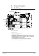
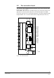
2 Product description 2.1 The CPU board The CPU board (Fig. 1) is the only board that composes the Cerban Splitter CBS-3. service pin LED S4 NC 2 3 4 5 6 7 8 Neuron Chip Reset Flash EPROM Service Diagnostic RAM UART1 UART UART3 TX CPU TX RX UART TX RX UART4 S1 RX RX UART2 8 7 6 5 4 3 2 1 RTC TX 8 7 6 5 4 3 2 1 S2 1 2 3 4 5 6 7 8 S3 Fig.
2.2 The connection board The connection board (CD96811) has two connectors. One is used to insert the CPU, the other is not used in CBS-3. All the UARTs, from 1 to 4, are accessible through screw connectors located on the right side of the connection board. Only the TX, RX and GND signals are available. In the lower right corner of the connection board there is the power supply block with two pins marked + and -. You must connect here the voltage source (10 to 30 V d.c.).
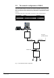
2.3 The network configuration of CBS-3 The Cerban Splitter CBS-3 is inserted in the network configuration shown in Fig. 2.4. It allows to connect any device which uses the Cerban protocol to two independent serial lines. The two lines can be connected to any device able to understand the Cerban protocol. The following table sums up the UARTs connections to other network elements.
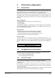
3 CPU board configuration 3.1 Introduction On the CPU board you can find four groups of dip-switches, numbered from S1 to S4. A fifth block can be found on the expansion board if it is installed. The dip-switches replace the jumpers that were used on the CBS-3 for configuration purposes. We will refer in this document to dip-switches with a double numbering convention: the fist number refers to the block the dip-switch belongs to, the second number is the switch position inside the block.
In a CBS-3 up to six UART are available and so 18 dip-switches are reserved (Actually only four of them are available). They are divided into groups of three. Each group can assume the value corresponding to the subsystem you want connect. SUBSYSTEM DIP-SWITCHES MSB OFF OFF OFF no subsystem CS11/CZ10/CC60 CS4/CZ12 OFF OFF ON LSB OFF ON OFF Tab. 2 Subsystem selection UART 1 2 3 4 DIP-SWITCHES MSB S1.6 S2.4 S3.2 S3.8 S1.5 S2.3 S3.1 S3.7 LSB S1.4 S2.2 S2.8 S3.6 Tab.
4 Hardware installation 4.1 Inside the CS4 In the CS4 intrusion detection control unit the gateway can be mounted on some of the standard housings. You need: § 2 plastic spacers § 2 self-tapping screws § 4 metal spacers § 2 short screws § 2 long screws § 2 board supports Fig. 4 Inside the CS4 7 Siemens Building Technologies Cerberus Division e1148c 06.
4.2 Inside the CS11 In the CS11 intrusion detection control unit the gateway can be mounted on some of the standard housings. You need: § 4 plastic spacers § 4 self-tapping screws § 2 board supports Fig. 5 Inside the CS11 4.3 Power supply The gateway GW-21 is powered using the connector located on the connection board (Please refer to Fig. 2). Please pay attention to pin polarities. The supply voltage must be in the range 10 to 30 V d.c. 8 Siemens Building Technologies Cerberus Division e1148c 06.
5 Cables and connections 5.1 Connection to GW-20 The figure below shows how to connect the Cerban Splitter CBS-3 to the Gat eway GW20, to transmit messages to the CMS/LMS monitoring system. Only UARTs 3 and 4 can be connected to the Gateway. CBS-3 UART4 UART3 UART2 UART1 18 17 16 15 14 13 12 GND 11 Rx4 10 Tx4 9 GND 8 Rx3 7 Tx3 6 GND 5 Rx2 4 Tx2 3 GND 2 Rx1 1 Tx1 Male connector 1 6 2 3 4 7 8 9 5 Net-M Pad in GW-20 Fig. 6 GW-21/GW-20 connection (screw terminal block) 5.
5.3 Connection to an user-provided device The serial line getting out of the CBS-3 uses the Cerban protocol. Be sure the device you connect to it is able to unde rstand Cerban protocol. The user-provided device can be connected to UARTs 3 and 4 only. These CBS-3 lines are master lines and so the user-provided device must act as a slave . CBS-3 UART4 UART3 UART2 UART1 18 17 16 15 14 13 12 GND 11 Rx4 10 Tx4 9 GND 8 Rx3 7 Tx3 6 GND 5 Rx2 4 Tx2 3 GND 2 Rx1 1 Tx1 GND Tx Rx User provided device Fig.
7 JUMPER FUNCTION S1.1 S1.4 S1.5 S1.6 S1.7 S1.8 S2.1 S2.2 S2.3 S2.4 S2.5 S2.6 S2.7 S2.8 S3.1 S3.2 S3.3 S3.4 S3.5 S3.6 S3.7 S3.8 S4.2 S4.3 S4.
Keyword index A G Asynchronous board 1 GW-00 1 C L CC60 6 Cerban vitality 6 CMS 1 Connection board 3 CPU board 2, 5 CS11 1, 4, 5, 6, 8 CS4 6, 7, 8 CZ10 1, 6, 8 CZ12 1, 6 LMS 1 D S Dip-switch 6 Subsystem setting 5 E T EPROM 5 Traffic 6 M Message traffic 6 P Power supply 8 F Flash EPROM 5, 6 1 Siemens Building Technologies Cerberus Division 06.
Siemens Building Technologies AG Cerberus Division CH-8708 Männedorf Alte Landstrasse 411 Tel. +41 1 - 922 61 11 Fax +41 1 - 922 64 50 www.cerberus.ch Siemens Building Technologies Cerberus Division Cerberus Security for People and Assets Replaces e1148b Doc.no Edition: e1148c 06.