GW20 GW20 Configurator Document No. Edition Supersedes e1730 02.
Table of contents Table of contents 1 Overview _____________________________________________ 3 1.1 Who this manual is for __________________________________________ 3 1.2 Document structure ____________________________________________ 3 1.3 Related Publications____________________________________________ 4 2 Introduction ___________________________________________ 5 3 How to install the software_______________________________ 6 4 The User Interface ______________________________________ 9 4.
Overview 9 Firmware manager_____________________________________29 10 The EPROM generation________________________________32 11 Help menu __________________________________________33 11.1 The software version _________________________________________ 33 11.2 The Firmware version _________________________________________ 33 II Data and design subject to change without notice. Supply subject to availability © Copyright by CERBERUS AG, CH-8708 Männedorf, Switzerland 1995 02.98 e1730.
Overview 1 Overview The Integrator Project Configurator GW 20 is a software intended to allow easy and quick configuration of Cerberus Dati network devices and in particular of GW 20. This manual describes the software used to configure the EPROMs needed by the Gateway GW-20 to operate properly. 1.1 Who this manual is for This manual is addressed to Cerberus personnel who must prepare the Gateways to fit the specific customer requirements. 1.
Overview 1.
Introduction 2 Introduction The software lets arrange in a graphical way the elements that build up any installation, i.e. project, building and subsystems installed. The project corresponds to the Site in LMS terms. A project is composed by all the safety and security systems that are needed to control and monitor a single installation that acts as a unity.
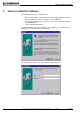
How to install the software 3 How to install the software The installation procedure is straightforward: • insert the first diskette of the diskette set into the floppy disk drive OR insert the CD ROM that contains the program in the CD ROM drive • from the Settings option of the Start menu, select the Control Panel and then Install Applications • run the SETUP.EXE program The installation procedure copies the files to your hard disk and creates the corresponding icon in the Start menu of Windows 95.
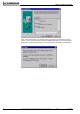
How to install the software Next step is to define where the program will be installed. The installation procedure suggests a default directory. But you can obviously change it using the Browse button. A file dialog box is shown that lets you select the directory in which to install the software. You are the prompted for a name that identifies the GW 20 configurator icon in the Start menu. As usual, you can leave the default choice or type your own.
How to install the software Only at this point the file copy actually starts. A progress meter shows the process status. You can stop at any moment the installation by clicking on the Cancel button. A dialog box is shown that prompts you for continuing the installation or abandoning it. 8 Data and design subject to change without notice. Supply subject to availability © Copyright by CERBERUS AG, CH-8708 Männedorf, Switzerland 1995 02.98 e1730.
The User Interface 4 The User Interface To run the GW 20 Configurator, you have to click on the corresponding icon in the Start menu of Windows 95. The GW 20 Configurator opens a main window that encloses a work area. In the work area are contained the windows that list the current projects, marked „Project Tree n. x“where x is a sequential number that identifies the window. You can have multiple windows that list the same database of projects.
The User Interface The configurator complies with Windows GUI rules and therefore its use is immediate to everyone that is confident with the user interface. The projects are represented as a gerarchical tree of objects. The root of the tree is by default a structure named „Projects“, but both projects and building can be transformed into the root of the tree with a menu option. The tree structure can be compacted or expanded just by clicking on the item you wish to contract/expand.
Projects: load, print and save 5 Projects: load, print and save The projects can be managed as units and you can save a configured project, load an existing project and document it by printing. 5.1 To save a project While you add elements to your project, they are automatically saved on disk and therefore there is no risk of data loss in case of accidental power down or failure of the computer you are working on.
Projects: load, print and save A further dialog window shows and displays: • the projects you selected for archiving • the name of the compressed file where all the selected archives will be copied • the target driver where the file will be created • a file dialog box that lets you select the directory where to create the compressed file You are informed about the disk space needed by the archived projects and the disk space available on the chosen unit.
Projects: load, print and save 5.2 To load a project The archived projects can be recovered and made active by loading them. To load a project: 1. Select File / Load from the main menu 2. a dialog box opens 3. you can select the zip file either typing the file name with the full path in the topmost field or by clicking on the button with ellipsis and selecting the file from the file dialog that opens. 4. in the leftmost field are listed the projects archived in the selected zip file.
Projects: load, print and save 5.3 To print a project To fully document the configuration, you can print project data on paper. The print option can be accessed through the Main menu, selecting File / Print. A dialog window opens, prompting for the print of sites or subsystems. You can preview the printed page (click on Print Preview button) or send directly the document to the printer (click on Print button). 14 Data and design subject to change without notice.
Projects: load, print and save 5.4 Print preview The Print Preview displays the page to be printed. Using the buttons in the lower part of the screen you can: • scroll page using the arrow buttons, if the documents is composed by more than one page • magnify the document to better examine parts of it • send the document to the printer • export the document to a file • export the document to a mailbox • close the preview window and revert to the project editing 5.4.
The Project Nodes 6 The Project Nodes When the Configurator is started the first time, it displays only one Project Tree and inside it one icon, named Projects. This icon is the first node of the Configurator and the root of everything else, at least as long as you do not modify the root. Every projects, building or subsystem is a node in the Configurator. You can add or delete nodes and modify their properties. 6.
The Project Nodes 6.3 To add a subsystem To add a subsystem you should: • select one of the site icons • select the menu option Site Node / Add subsystem • A dialog window opens: This dialog window lets you configure the subsystem. You must type the subsystem description and choose from the drop down list the subsystem you wish to configure. The other fields are filled in with default value you can modify, within certain constraints.
The Project Nodes 6.5 To delete a node To delete a node, whether it is a project, a site or a subsystem, you should: • select the node icon • select the menu option that could be Project Node, Site Node or Subsystem Node and in the drop down menu select the Delete option. A dialog box that prompts for confirmation is displayed. • If you answer Yes, the subsystem, site or project is removed from the Configurator.
Subsystem properties 7 Subsystem properties Subsystems are the physical devices installed in the field and their properties change according to the type of device you are dealing with. The window that is displayed shows six fields, that are: • Description : a text up to 50 characters long that is shown in the Project Tree window and describes the subsystem • Type: the type of installed subsystems. The content of this field is taken from a list of supported subsystems listed below 1. AGFA (Alcatel PBX) 2.
Subsystem properties CBA-NORGE • CBA/0 872 points • CBA/1 1229 points • CBA/2 1705 points • CBA/3 2181 points • CBA/4 3609 points • CBA/5 5037 points • CBA/6 6465 points • CBA/7 8369 points CC11 • CC11/0 64 zone/elements • CC11/1 128 zone/elements • CC11/2 256 zone/elements • CC11/3 512 zone/elements • CC11/4 768 zone/elements • CC11/5 1024 zone/elements CC60 • CC60 • NCRS/0 24 Input V. 3.0 • NCRS/1 18 Input/8 Output V. 3.0 • NCRS/2 Diagnostic • NCRS/3 24 Output V. 3.
Subsystem properties CZ10 • CZ10 - 24 zones • CZ10 - 48 zones • CZ10 - 72 zones • CZ10 - 96 zones • CZ10 - 96 zones + Gas/Ext+Tech • CZ10 - 96 zones + Gas/Ext+Tech 8 lines • CZ10 - 96 zones + Gas/Ext+Tech 16 lines • CZ10 - 96 zones + Gas/Ext+Tech 24 lines CZ12 • CZ12 - Intrusion C.U. • CZ12 - Intrusion C.U.
Subsystem properties SE902 • SE902/0 2 doors 2 VIP 1 MI6 • SE902/1 2 doors 2 VIP 4 MI6 • SE902/2 2 doors 2 VIP 8 MI6 • SE902/3 2 doors 1 VIP 8 MI6 4 RO STT-10 • STT-10 • STT-11 • STT-11 TVCC COMERSON • TVCC COMERSON • Local address: this number identifies the control panel in the local network; it applies to some protocols and the value range depends on the protocol. • Protocol: depends on the subsystem chosen and in most cases it cannot be changed.
Subsystem properties The following table sums the available values of protocols, local addresses and baud rates that can be used during the subsystem properties setup. Subsystem e1730.
Gateway Configuration 8 Gateway Configuration The Gateway is one among the many subsystems you can add to a Site, but it is quite peculiar for its role in the LMS networks. The Gateway acts both as a network concentrator and a message dispatching centre, with autonomous processing power and the capability to report to the user through the LMS Monitoring System. When you include a Gateway in the list of subsystems, it is just shown with a different icon.
Gateway Configuration 8.1.3 How to change the Pad type In the general Gateway configuration environment, choose in the drop down list of Pad types a different type. The Configuration Tree will change accordingly. 8.1.4 How to change the Pad protocol In the general Gateway configuration environment, choose in the drop down list of Pad protocols a different protocol. The Configuration Tree will change accordingly. 8.
Gateway Configuration 8.3 Line configuration The configuration of individual lines can be performed selecting with the mouse a line in the Configuration Tree and then set the field values in the right part of the work area.
Gateway Configuration 8.4 Device Configuration The configuration of the devices deals only with their protocol (that usually cannot be changed) and the baud rate. You must select with the mouse a device in the Configuration Tree and then set the field values in the right part of the work area. e1730.doc Data and design subject to change without notice. Supply subject to availability © Copyright by CERBERUS AG, CH-8708 Männedorf, Switzerland 1995 02.
Gateway Configuration 8.5 Routing Tables The routing tables allow the redirection of messages generated by the subsystems to the LMS monitoring system. The routing tables can be accessed either at Gateway level and Line level. The tab shows that we are configuring the Routing Table for Line 3 This is the routing table currently selected.
Firmware manager 9 Firmware manager The firmware versions are frequently changed due to modification in the protocols or improvement of software. Therefore the Configurator has a tool, called Firmware manager, that allows the end-user to update the firmware versions he/she is currently working on. To access the Firmware Manager, select this option from the Tools menu. The following dialog box will appear: The file firmwnew.txt contains the most updated information about the firmware version.
Firmware manager The File menu lists five options: • New • Update • Delete • Set predefined Firmware • Exit New lets define a new firmware set. When you access this option or the Update option, a dialog box opens prompting you to identify the directory that contains the new firmware versions. The information about the new or updated firmware version will be copied in the directory stated in the uppermost field, that you cannot change.
Firmware manager If you confirm the update process, the absolute file conversion starts and a progress bar is shown. e1730.doc Data and design subject to change without notice. Supply subject to availability © Copyright by CERBERUS AG, CH-8708 Männedorf, Switzerland 1995 02.
The EPROM generation 10 The EPROM generation The Configurator generates the absolute files that can be sent to an EPROM programmer in order to burn the EPROMs to be installed on the Gateway Pads. The absolute file generation is quite a lengthy one and must be performed only when you are confident the configuration process is completed. To access this procedure, select in the Tool menu the option EPROMS, a dialog box is shown.
Help menu 11 Help menu 11.1 The software version To verify the version of the GW 20 Configurator you are currently using, select in the Help menu the option labelled About GW20 Configurator. A dialog box with the version of the installed software is shown. 11.2 The Firmware version To verify the version of firmware you are currently using, select in the Help menu the option labelled About Firmware list. A dialog box with the version of the current firmware is shown. e1730.