
Data Sheet for Product


3
Building Technologies
A6V10281972_c_en_--
Fire safety and security products
07.2012
Installation
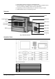
Fig.3 Installation size (in:mm)
Installation must comply with the local regulation!
1. Ensure the wall is dry, clean, flat and firm in which the controller is installed.
2. Chose a proper installation location to make sure the front door can be opened smoothly.
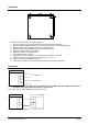
3. Mark the drillings for 4 installation holes on the wall. (Fig. 2-1)
4. Drill the holes, put expansion bolts in and insert the M6 screws.
5. Break the cable entries on the controller.
6. Hang the controller over those screws.
7. Insert cables into the controller.
8. Open the front panel and tighten the screws to fix the controller on the wall.
9. Connect cables to the terminals according to Fig. 4, 5, 6, 7, 8, 9.
10. Install and secure the batteries properly.
11. Close the front panel. Lock it with special tools and store the tools in safe place.
Connection
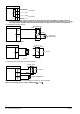
FC18
BP1
BS1
AS1
AP1
To Line 1
+
_
_
+
To Field device
To Field device
Note: In loop mode, wires from BP1 must end at AP1; wires from BS1 must end at AS1. The connection
of field devices (except FDCL181 isolator) is polarity free.
Fig. 4 Line card connection diagram (the same for Line 2)
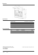
FC18
FTL
FTH
To FRT
_
+
CAN-
CAN+
FT1810
_
+
Fig. 5 FRT connection diagram