
Data Sheet for Product


4
Building Technologies
A6V10281972_c_en_--
Fire safety and security products
07.2012
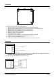
FC18
FCH
FCL
FCL
FCH
To Controller
+
_
_
+
To Controller
To Controller
Note: Ensure positive and negative connections are properly in place, FC18-Bus is polarity sensitive.
Connect a 120Ω resistor as monitoring resistor. It must be connected to the end of the line. ( It can
be set by the two-digit Dip-switch on the main board, see “Dip-switch connection configuration” )
Fig. 6 Network connection diagram
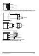
Visible and
audible device
FC18
To NAC
NAC+
NAC-
Red
Black
Orange
Black
20K
resistor
NAC-EOL-FC18
Fig. 7
NAC connection
diagram
FC18 To Input/Output
IO+
IO-
Dry Contact
Output Input
1K
10K
IO-EOL-FC18
Orange
Black
Red
Black
Fig. 8 Main board input/output connection diagram
KI1
+
_
+
FC18
KC1
KO1
To Int. Chan. 1
Dry Contact
1K
10K
IO-EOL-FC18
Orange
Black
Red
Black
Output(40mA@24VDC)
Fig. 9 Interlocking panel connection diagram (the same for other channels)
Note: the load range of each input is 24VDC, 600
Ω
– 1.2k
Ω