
Installation Instructions

3
Building Technologies A6V10436766_b_en_--
Fire Safety 2014-11-27
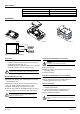
Fig. 4 Input/output module jumper position J2
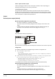
Fig. 5 Connection diagram for inverted operation, e.g. when used as door retainer.
In inactive status the 24 V DC are permanently applied to the output and may keep a door
open, for example. When the output is switched to active, the output goes into "open" status
(= no 24 V DC voltage) and the door is closed.
Comment:
In this example, the door would also close if the 24 VDC supply were to fail, e.g. due to a line
problem (short circuit, open line).
Configuration
Under inverted mode, the following configurations are possible through controller or
configuration tools :
l After activating the output remains:
‒ Steady output
‒ Pulse output: How long the contact remains active can be configured by controller or
configuration tools (pulse duration).
l Failsafe behavior when the FD18-BUS detector line is current-free or in degraded mode.
The error behavior defines the position of the output through controller or configuration
tools in case of an error :
‒ Off: Output remains in the same position as before the error
‒ Activation: Output is activated in case of an error
‒ Deactivation: Output is deactivated in case of an error
The controller does not monitor external equipment status (activated/inactivated).
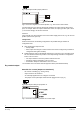
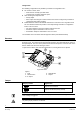
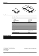
Dry contact output
Potential-free contact (Output not monitored)
- Be used for controlling (e.g. closing a door).
- Output control is not monitored.
- An externally supplied 24 V DC voltage is not needed.
- The jumper on the input/output module must be plugged onto J1 (Fig. 6).
Fig.6 Input/output module jumper position J1
Fig. 7 Connection diagram for potential-free contact output