
User Manual


Mounting / Installation
Connection diagram, addressed
5
26 | 38
Building Technologies
A6V10218037_n_en_
--
Fire Safety
2019
-
03
-
25
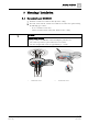
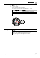
5.5.1 Auxiliary terminals DBZ1190-AA/-AB
Use the following auxiliary terminals for multiple connections:
● DBZ1190-AB connection terminal 0.5…2.5 mm²
● DBZ1190-AA micro terminal 0.28…0.5 mm²
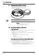
A defective contact may occur when replacing a plugged
-
in conductor cross
-
section of 2.5 mm
2
with conductor cross-sections of 0.5…0.8 mm
2
.
See also
2 Connection terminal DBZ1190-AB [➙ 18]
2 Micro terminal DBZ1190-AA [➙ 18]
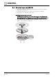
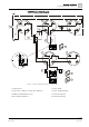
5.6 Connection diagram, addressed
Cables and topology
● The connection is established from base to base using twisted or non-twisted
wire pairs.
● Wherever possible use twisted, unshielded cables.
● Shielded cables are only required in special cases, such as strong high-
frequency fields.
● You have the option of using the following types of line:
– Loops
– Stub lines
– Stub line as a branch of a loop
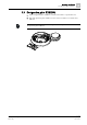
Connecting external alarm indicators FDAI91 / FDAI92 / FDAI93
Observe the following points when connecting external alarm indicators:
● Wherever possible use twisted, unshielded cables.
● Connect a maximum of two external alarm indicators to one detector.
● If a cable with shielding is used to connect the external alarm indicator, this
shielding must be linked to the shielding of the detector bus.
The shielding must not be linked to the external alarm indicator itself.