
User Manual
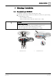


Mounting / Insta
llation
Connection diagram, addressed
5
27 |
38
Building Technologies
A6V10218037_n_en_
--
Fire Safety
2019
-
03
-
25
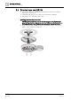
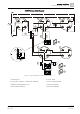
C-NET connection diagram
Figure 4: Connection diagram for addressed detector lines
1 Control panel 5 Cable –EAI6
2 Detector base DB72x, sounder base DBS720 6 Cable –EAI5 (optional)
3 Auxiliary terminal DBZ1190-xx 7 Short circuit (error)
4 External alarm indicator 8 Short circuit (error)
1a
1b
5 6
1a
1b
5 6
1a 1b
5 6
1a 1b
5 6
1a
1b
5 6
+
–
+
–
+
–
2 2
2
2
2
1
3
4
4
+
–
7
8
5
6
5 6
+
–
4
3
3