
Operating Instructions

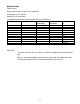


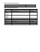
Table Of Contents
- Fire Alarm Control Panel
- Model FC901
- TABLE OF CONTENTS
- INTRODUCTION
- DESCRIPTIONS
- SLC grounding detection threshold
- CONTROL PANEL OPERATION
- CONTROL PANEL INSTALLATION
- SYSTEM WIRING
- AC Connection
- Battery Connection
- WIRING
- Control Panel Wiring Overview
- Wiring Entering Enclosure
- Install Wiring
- Wiring Separation
- Internal Structure
- Power Supply and Battery Wiring
- Status Relays
- Auxiliary Power Outputs Wiring
- NAC Wiring
- Serial Interface Circuit (UFP)
- Serial Remote Device Wiring Overview
- SLC Addressable Device Circuit
- SLC Addressable Device Wiring Diagrams
- Optional City Tie/Leased Line
- DACT Wiring
- PROGRAMMING THE CONTROL PANEL
- MAINTENANCE
- APPENDIX-A: REFERENCE DATA
- APPENDIX-B: COMPATIBLE DEVICES
- APPENDIX-C: TROUBLESHOOTING
- APPENDIX-D: ALARM VERIFICATION
- APPENDIX-E: APPLICATION SPECIFIC DETECTION
- APPENDIX-F: TESTING/MAINTENANCE
- APPENDIX-G: LCD, CONTROLS AND INDICATORS
- APPENDIX-H: OUTPUT FEATURES
- APPENDIX-I: PAS / PRE-SIGNAL
- APPENDIX-J: DACT INFORMATION OVERVIEW
- APPENDIX-K: DRIFT COMPENSATION
- APPENDIX-L: RELEASING OPERATION
- APPENDIX-M: GLOSSARY
- APPENDIX-N: PAD-4 WIRING INSTRUCTION
- APPENDIX-O: ISOLATOR SUPPORT
16
City Tie Circuits
Supply Input:
Voltage: 26 VDC
18 – 28 VDC for battery
Current: Max. 0.4 A
Supervised
Output:
City Tie-Output 1
Normal output voltage: 19-28 VDC (open circuit condition)
Supervisory current: 1 mA
Maximum trip current: 400 mA
Maximum coil plus wire resistance: 22.5 Ω
Leased line-Output 1
Normal output voltage: 19-28 VDC (open circuit condition)
Trouble output voltage: 0 V
Alarm output voltage: -(19-28) VDC (open circuit condition)
Maximum wire resistance: 2-5 kΩ
Maximum short circuit current: 25 mA
Leased line-Output 2
Normal output voltage: 19-28 VDC (open circuit condition)
Supervisory output voltage: -(19-28) VDC (open circuit condition)
Maximum wire resistance: 2-5 kΩ
Maximum short circuit current: 25 mA