
Operating Instructions

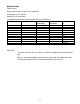


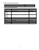
Table Of Contents
- Fire Alarm Control Panel
- Model FC901
- TABLE OF CONTENTS
- INTRODUCTION
- DESCRIPTIONS
- SLC grounding detection threshold
- CONTROL PANEL OPERATION
- CONTROL PANEL INSTALLATION
- SYSTEM WIRING
- AC Connection
- Battery Connection
- WIRING
- Control Panel Wiring Overview
- Wiring Entering Enclosure
- Install Wiring
- Wiring Separation
- Internal Structure
- Power Supply and Battery Wiring
- Status Relays
- Auxiliary Power Outputs Wiring
- NAC Wiring
- Serial Interface Circuit (UFP)
- Serial Remote Device Wiring Overview
- SLC Addressable Device Circuit
- SLC Addressable Device Wiring Diagrams
- Optional City Tie/Leased Line
- DACT Wiring
- PROGRAMMING THE CONTROL PANEL
- MAINTENANCE
- APPENDIX-A: REFERENCE DATA
- APPENDIX-B: COMPATIBLE DEVICES
- APPENDIX-C: TROUBLESHOOTING
- APPENDIX-D: ALARM VERIFICATION
- APPENDIX-E: APPLICATION SPECIFIC DETECTION
- APPENDIX-F: TESTING/MAINTENANCE
- APPENDIX-G: LCD, CONTROLS AND INDICATORS
- APPENDIX-H: OUTPUT FEATURES
- APPENDIX-I: PAS / PRE-SIGNAL
- APPENDIX-J: DACT INFORMATION OVERVIEW
- APPENDIX-K: DRIFT COMPENSATION
- APPENDIX-L: RELEASING OPERATION
- APPENDIX-M: GLOSSARY
- APPENDIX-N: PAD-4 WIRING INSTRUCTION
- APPENDIX-O: ISOLATOR SUPPORT

24
CONTROL PANEL INSTALLATION
PARTS SUPPLIED – FC901
FC901 Enclosure Assembly FH901-U3(Black)/FH902-U3(Red)
FC901 Main Board Assembly FCM901-U3 / FCM901-L3
Power Supply Assembly FP2011-U1
FC901 City Tie Module Assembly (optional) FCI2020-U1
FC901 Configuration Kit (optional) FXS901-U3
FC901 Spare HW Kit FX901-S1
1. FC901 Enclosure Package
FC901 black enclosure
Description
Qty
FC901 enclosure black
1
Installation instruction
1
T45 key
2
#8-32 grounding cable nut
2
FC901 red enclosure
Description
Qty
FC901 enclosure
1
Installation instruction
1
T45 key
2
#8-32 grounding cable nut
2
2. FC901 Main Board Package
Description
Qty
FC901 main board
1
FC901 main board support frame
1
FC901 English film
1
FC901 English strip
1
FC901 rubber key
1
FC901 battery bracket left (optional)
1
FC901 battery bracket right (optional)
1
FC901 battery cable
1
FC901 battery cable to main board
1
FC901 earth cable
1
Terminal block 2 pin
8
Terminal block 3 pin
4
Terminal block 4 pin
2
FC901 cable ties
6
FC901 main board installation instruction
1
FC901 wiring diagram
1
#8-32 x 3/8” screws
8
#4-40 x 1/4” screws
19
Grounding cable
1