
Operating Instructions
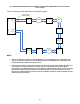

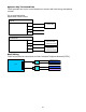


Table Of Contents
- Fire Alarm Control Panel
- Model FC901
- TABLE OF CONTENTS
- INTRODUCTION
- DESCRIPTIONS
- SLC grounding detection threshold
- CONTROL PANEL OPERATION
- CONTROL PANEL INSTALLATION
- SYSTEM WIRING
- AC Connection
- Battery Connection
- WIRING
- Control Panel Wiring Overview
- Wiring Entering Enclosure
- Install Wiring
- Wiring Separation
- Internal Structure
- Power Supply and Battery Wiring
- Status Relays
- Auxiliary Power Outputs Wiring
- NAC Wiring
- Serial Interface Circuit (UFP)
- Serial Remote Device Wiring Overview
- SLC Addressable Device Circuit
- SLC Addressable Device Wiring Diagrams
- Optional City Tie/Leased Line
- DACT Wiring
- PROGRAMMING THE CONTROL PANEL
- MAINTENANCE
- APPENDIX-A: REFERENCE DATA
- APPENDIX-B: COMPATIBLE DEVICES
- APPENDIX-C: TROUBLESHOOTING
- APPENDIX-D: ALARM VERIFICATION
- APPENDIX-E: APPLICATION SPECIFIC DETECTION
- APPENDIX-F: TESTING/MAINTENANCE
- APPENDIX-G: LCD, CONTROLS AND INDICATORS
- APPENDIX-H: OUTPUT FEATURES
- APPENDIX-I: PAS / PRE-SIGNAL
- APPENDIX-J: DACT INFORMATION OVERVIEW
- APPENDIX-K: DRIFT COMPENSATION
- APPENDIX-L: RELEASING OPERATION
- APPENDIX-M: GLOSSARY
- APPENDIX-N: PAD-4 WIRING INSTRUCTION
- APPENDIX-O: ISOLATOR SUPPORT

53
APPENDIX-A: REFERENCE DATA
This appendix provides reference for the following topics:
Wire selection guides
Battery size calculations
WIRE SELECTION GUIDES
Resistance of Solid Copper Wire
AWG
Ohm per Thousand Feet*
18
8.08
16
5.08
14
3.19
12
2.01
*NEC Chapter 9, Table 8.
Addressable Device Circuit Wire Selection Guide
Each addressable device circuit must meet the following requirements:
Total loop resistance – 50 Ohm maximum with 50 devices
Total loop capacitance - 0.5 uF max line to line per km and 1.0 uF max line to shield per km
Note:
• The terminal blocks of Siemens SLC devices are rated for a maximum of 14AWG wire.