
Operating Instructions
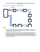

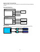


Table Of Contents
- Fire Alarm Control Panel
- Model FC901
- TABLE OF CONTENTS
- INTRODUCTION
- DESCRIPTIONS
- SLC grounding detection threshold
- CONTROL PANEL OPERATION
- CONTROL PANEL INSTALLATION
- SYSTEM WIRING
- AC Connection
- Battery Connection
- WIRING
- Control Panel Wiring Overview
- Wiring Entering Enclosure
- Install Wiring
- Wiring Separation
- Internal Structure
- Power Supply and Battery Wiring
- Status Relays
- Auxiliary Power Outputs Wiring
- NAC Wiring
- Serial Interface Circuit (UFP)
- Serial Remote Device Wiring Overview
- SLC Addressable Device Circuit
- SLC Addressable Device Wiring Diagrams
- Optional City Tie/Leased Line
- DACT Wiring
- PROGRAMMING THE CONTROL PANEL
- MAINTENANCE
- APPENDIX-A: REFERENCE DATA
- APPENDIX-B: COMPATIBLE DEVICES
- APPENDIX-C: TROUBLESHOOTING
- APPENDIX-D: ALARM VERIFICATION
- APPENDIX-E: APPLICATION SPECIFIC DETECTION
- APPENDIX-F: TESTING/MAINTENANCE
- APPENDIX-G: LCD, CONTROLS AND INDICATORS
- APPENDIX-H: OUTPUT FEATURES
- APPENDIX-I: PAS / PRE-SIGNAL
- APPENDIX-J: DACT INFORMATION OVERVIEW
- APPENDIX-K: DRIFT COMPENSATION
- APPENDIX-L: RELEASING OPERATION
- APPENDIX-M: GLOSSARY
- APPENDIX-N: PAD-4 WIRING INSTRUCTION
- APPENDIX-O: ISOLATOR SUPPORT

55
SLC Current Draw Break down
SLC Current Draw Components
Standby (A)
Alarm (A)
HFP-11
0.00140
0.00140
HFPO-11
0.00140
0.00140
HFPT-11
0.00140
0.00140
OOHC941
0.00075
0.00075
OOH941
0.00068
0.00068
OH921
0.00030
0.00030
OP921
0.00030
0.00030
HI921
0.00028
0.00028
FDCIO42
0.00120
0.00120
HMS
0.00140
0.00140
HTRI-S
0.00140
0.00140
HTRI-D
0.00140
0.00140
HTRI-R
0.00140
0.00140
HZM
0.00140
0.00140
HCP
0.00140
0.00140
ILED
0.00140
0.00140
FDOOTC441
0.00075
0.00075
FDOOT441
0.00068
0.00068
FDOT421
0.00030
0.00030
FDO421
0.00030
0.00030
FDT421
0.00028
0.00028
ABHW-4B
0.00030
0.00030
ABHW-4S
0.00030
0.00030
XTRI-R
0.00050
0.00075
XTRI-D
0.00050
0.00095
XTRI-M
0.00050
0.00050
XTRI-S
0.00050
0.00065
ILED-XC
0.00050
0.00050
ILED-XW
0.00050
0.00050
TSM-1X
0.00050
0.00050
PAD-5-MB
0.00075
0.00075
PAD-5-CLSA
0.00125
0.00125
PAD-5-CDC
0.00075
0.00075
Pull station
0.00050
0.00050
Total Standby Current = 0.1590 + C2 + C4 + 0.0017 (if used)
Total Alarm Current = 0.1864 + C1 + C3 + C5 + 0.0158 (if used)
Where
C1 = NAC1 current + NAC2 current, should be less or equal to 2.5 A.
C2 = ∑quantity of each type of detector x standby current/each
C3 = ∑quantity of each type of detector x alarm current/each
C4 = External device current draw through Aux1 and Aux2 in standby stage, either one of
Aux1 and Aux2 should be less than or equal to 0.75 A.
C5 = External device current draw through Aux1 and Aux2 in alarm stage, either one of Aux1
and Aux2 should be less than or equal to 0.75 A.