
Operating Instructions

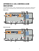


Table Of Contents
- Fire Alarm Control Panel
- Model FC901
- TABLE OF CONTENTS
- INTRODUCTION
- DESCRIPTIONS
- SLC grounding detection threshold
- CONTROL PANEL OPERATION
- CONTROL PANEL INSTALLATION
- SYSTEM WIRING
- AC Connection
- Battery Connection
- WIRING
- Control Panel Wiring Overview
- Wiring Entering Enclosure
- Install Wiring
- Wiring Separation
- Internal Structure
- Power Supply and Battery Wiring
- Status Relays
- Auxiliary Power Outputs Wiring
- NAC Wiring
- Serial Interface Circuit (UFP)
- Serial Remote Device Wiring Overview
- SLC Addressable Device Circuit
- SLC Addressable Device Wiring Diagrams
- Optional City Tie/Leased Line
- DACT Wiring
- PROGRAMMING THE CONTROL PANEL
- MAINTENANCE
- APPENDIX-A: REFERENCE DATA
- APPENDIX-B: COMPATIBLE DEVICES
- APPENDIX-C: TROUBLESHOOTING
- APPENDIX-D: ALARM VERIFICATION
- APPENDIX-E: APPLICATION SPECIFIC DETECTION
- APPENDIX-F: TESTING/MAINTENANCE
- APPENDIX-G: LCD, CONTROLS AND INDICATORS
- APPENDIX-H: OUTPUT FEATURES
- APPENDIX-I: PAS / PRE-SIGNAL
- APPENDIX-J: DACT INFORMATION OVERVIEW
- APPENDIX-K: DRIFT COMPENSATION
- APPENDIX-L: RELEASING OPERATION
- APPENDIX-M: GLOSSARY
- APPENDIX-N: PAD-4 WIRING INSTRUCTION
- APPENDIX-O: ISOLATOR SUPPORT

73
APPENDIX-H: OUTPUT FEATURES
Output Activation- and Deactivation- Delays
Each output device has a selection for Activation delay and Deactivation delay when it is
installed in the configuration. The Activation delay refers to the delay in which the output will
activate after the reception of its activation command. If the Activation delay is set to 0 (default
setting), the output immediately activates. The Deactivation delay refers to the delay in which
the output will deactivate after the reception of its deactivation command. If the Deactivation
delay is set to 0 (default setting), the output immediately deactivates.
Output device during activation delay will not respond to deactivate command. This means an
output device with activation delay will definitely be activated after receiving activate command.
Output device during deactivation delay will respond to activate command immediately and the
deactivation delay will be cancelled.
Assuming an output channel on SLC is configured to be interlocked by supervisory condition of
FACP with Activation Delay of 10s and Deactivation Delay of 10s. When FACP enters
supervisory condition at 00”00’, the output channel will be activated at 00”10’. Then if the
supervisory condition goes at 00”30’, the output channel will be deactivated at 00”40’.
OFF
ON
Output State
Activation
Delay
Deactivation
Delay
On Activate
Command
On
Deactivate
Command
Note:
• This function applies only to IO modules on SLC.