
Operating Instructions

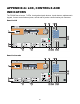


Table Of Contents
- Fire Alarm Control Panel
- Model FC901
- TABLE OF CONTENTS
- INTRODUCTION
- DESCRIPTIONS
- SLC grounding detection threshold
- CONTROL PANEL OPERATION
- CONTROL PANEL INSTALLATION
- SYSTEM WIRING
- AC Connection
- Battery Connection
- WIRING
- Control Panel Wiring Overview
- Wiring Entering Enclosure
- Install Wiring
- Wiring Separation
- Internal Structure
- Power Supply and Battery Wiring
- Status Relays
- Auxiliary Power Outputs Wiring
- NAC Wiring
- Serial Interface Circuit (UFP)
- Serial Remote Device Wiring Overview
- SLC Addressable Device Circuit
- SLC Addressable Device Wiring Diagrams
- Optional City Tie/Leased Line
- DACT Wiring
- PROGRAMMING THE CONTROL PANEL
- MAINTENANCE
- APPENDIX-A: REFERENCE DATA
- APPENDIX-B: COMPATIBLE DEVICES
- APPENDIX-C: TROUBLESHOOTING
- APPENDIX-D: ALARM VERIFICATION
- APPENDIX-E: APPLICATION SPECIFIC DETECTION
- APPENDIX-F: TESTING/MAINTENANCE
- APPENDIX-G: LCD, CONTROLS AND INDICATORS
- APPENDIX-H: OUTPUT FEATURES
- APPENDIX-I: PAS / PRE-SIGNAL
- APPENDIX-J: DACT INFORMATION OVERVIEW
- APPENDIX-K: DRIFT COMPENSATION
- APPENDIX-L: RELEASING OPERATION
- APPENDIX-M: GLOSSARY
- APPENDIX-N: PAD-4 WIRING INSTRUCTION
- APPENDIX-O: ISOLATOR SUPPORT

75
Pre-Signal
When an alarm causing device in a Pre-Signal input group is initiated, the alarm condition is
reported at the panel. Its associated NACs are not activated until the programmed
investigation delay has relapsed or 2
nd
Alarm is initiated anytime during the Pre-Signal delay
time (see figure below).
1
st
Alarm
Initiated
2
nd
Alarm
Initiated
Panel
Reset
Pre-Signal Delay time
Figure A
Figure B
When 2
nd
Alarm is
Initiated
Audible ON
Audible OFF
Audible ON
Audible OFF
Pre-Signal
Normal
Sequence
Pressing the reset button at anytime during the Pre-Signal sequence will initiate a reset
condition and restore the panel to stand-by state.