
Operating Instructions


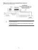
Table Of Contents
- Fire Alarm Control Panel
- Model FC901
- TABLE OF CONTENTS
- INTRODUCTION
- DESCRIPTIONS
- SLC grounding detection threshold
- CONTROL PANEL OPERATION
- CONTROL PANEL INSTALLATION
- SYSTEM WIRING
- AC Connection
- Battery Connection
- WIRING
- Control Panel Wiring Overview
- Wiring Entering Enclosure
- Install Wiring
- Wiring Separation
- Internal Structure
- Power Supply and Battery Wiring
- Status Relays
- Auxiliary Power Outputs Wiring
- NAC Wiring
- Serial Interface Circuit (UFP)
- Serial Remote Device Wiring Overview
- SLC Addressable Device Circuit
- SLC Addressable Device Wiring Diagrams
- Optional City Tie/Leased Line
- DACT Wiring
- PROGRAMMING THE CONTROL PANEL
- MAINTENANCE
- APPENDIX-A: REFERENCE DATA
- APPENDIX-B: COMPATIBLE DEVICES
- APPENDIX-C: TROUBLESHOOTING
- APPENDIX-D: ALARM VERIFICATION
- APPENDIX-E: APPLICATION SPECIFIC DETECTION
- APPENDIX-F: TESTING/MAINTENANCE
- APPENDIX-G: LCD, CONTROLS AND INDICATORS
- APPENDIX-H: OUTPUT FEATURES
- APPENDIX-I: PAS / PRE-SIGNAL
- APPENDIX-J: DACT INFORMATION OVERVIEW
- APPENDIX-K: DRIFT COMPENSATION
- APPENDIX-L: RELEASING OPERATION
- APPENDIX-M: GLOSSARY
- APPENDIX-N: PAD-4 WIRING INSTRUCTION
- APPENDIX-O: ISOLATOR SUPPORT

79
Done.
Scenario 3 – Must/Can
Alarm Event is set to Must Report on Account 1 and Can
Report on Account 2. Panel succeeds on Account 1 the
first time.
Step 1:
Panel goes into alarm.
Step 2:
Panel tries to send event
to Account 1 successful.
Y Account 1
Account 2
Step 3:
Panel does NOT attempt to send event to Account 2, since Account 2 is set for
Can Report and the event was transmitted to Account 1 successfully.