
Operating Instructions


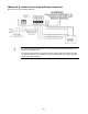
Table Of Contents
- Fire Alarm Control Panel
- Model FC901
- TABLE OF CONTENTS
- INTRODUCTION
- DESCRIPTIONS
- SLC grounding detection threshold
- CONTROL PANEL OPERATION
- CONTROL PANEL INSTALLATION
- SYSTEM WIRING
- AC Connection
- Battery Connection
- WIRING
- Control Panel Wiring Overview
- Wiring Entering Enclosure
- Install Wiring
- Wiring Separation
- Internal Structure
- Power Supply and Battery Wiring
- Status Relays
- Auxiliary Power Outputs Wiring
- NAC Wiring
- Serial Interface Circuit (UFP)
- Serial Remote Device Wiring Overview
- SLC Addressable Device Circuit
- SLC Addressable Device Wiring Diagrams
- Optional City Tie/Leased Line
- DACT Wiring
- PROGRAMMING THE CONTROL PANEL
- MAINTENANCE
- APPENDIX-A: REFERENCE DATA
- APPENDIX-B: COMPATIBLE DEVICES
- APPENDIX-C: TROUBLESHOOTING
- APPENDIX-D: ALARM VERIFICATION
- APPENDIX-E: APPLICATION SPECIFIC DETECTION
- APPENDIX-F: TESTING/MAINTENANCE
- APPENDIX-G: LCD, CONTROLS AND INDICATORS
- APPENDIX-H: OUTPUT FEATURES
- APPENDIX-I: PAS / PRE-SIGNAL
- APPENDIX-J: DACT INFORMATION OVERVIEW
- APPENDIX-K: DRIFT COMPENSATION
- APPENDIX-L: RELEASING OPERATION
- APPENDIX-M: GLOSSARY
- APPENDIX-N: PAD-4 WIRING INSTRUCTION
- APPENDIX-O: ISOLATOR SUPPORT

81
DACT COMPATIBLE ALARM COMMUNICATORS
The FC901-U3/-R3 DACT is also compatible with Alarm communicators that utilized different
communication technologies (IP and GSM technologies) to connect to compatible Receivers
using compatible protocol listed within this documentation.
COMPATIBLE ALARM COMMUNICATORS
Manufacturer
Model Number
Communication
Technology
Installation
Part Number
For installation
in
Telguard
TG-7FS
GSM
56044102
US
DMP
ICOMSLF
IP
-
US
NAPCO Starlink
SLE-LTEVI-FIRE
IP/GSM
-
US
NAPCO Starlink
SLE-LTEVI-CFB
IP/GSM
-
US
NAPCO Starlink
SLE-LTEVI-CFBPS
IP/GSM
-
US
NAPCO Starlink
SLE-LTEAI-CFBPS
IP/GSM
-
US
NAPCO Starlink
SLE-LTEAI-CFB
IP/GSM
-
US
NAPCO Starlink
SLE-LTEAI-FIRE
IP/GSM
-
US
B465
Bosch
IP/GSM
-
US
DSC
TL300CF
IP
29007636/29007842
Canada
DSC
LE4010CF
GSM
-
Canada
Notes:
◼ DACT is configured with the alarm communicator for other transmission
technologies, off-premise signaling for UL. DACT is used for off-premise signal
transmission for ULC.
◼ When using these alarm communicators, the DACT shall be configured for
Contact ID.
◼ When configuring the dialers, the Dialer Group Number needs to be
programmed to match the actuated Zone Number.
◼ Refer to the Alarm Communicator Installation Instruction for compatible
receivers.
◼ For US installations, wiring between the DACT and the alarm communicator
shall be within 20 feet, and in conduit.
◼ For Canadian configurations interconnection between the control unit and the
Alarm Communicator shall be in metallic conduit not exceeding 18 meters and
located in the same room.
◼ The C900V2 shall be installed in accordance with its installation instructions.
◼ For ULC passive off-premise communication, only one of the two combinations
can be configured: POTS & DSC TL300CF or POTS & DSC LE4010CF.
◼ If a combination of POTS and DSC communicator is configured, the POTS line
(“A”) must be the Primary; the DSC communicator shall have an input
connected to panel alarm relay.
◼ Refer to Telluar TG7GFS04 Installation Instructions for trouble report connection
with FACP and AC trouble delay.