
Data Sheet for Product
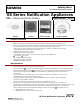


s Industry, Inc.
Building Technologies Division
Specifications – (continued)
– The selector switch for selecting the candela shall be tamper resistant and not accessible from the
front of the appliance
– Synchronization is possible when using the Siemens DSC sync modules, FS-250 panel, XLS panel,
or PAD-3 power supply with built-in sync protocol
– The strobes shall not drift out of synchronization at any time during operation – If the sync
module or Power Supply fails to operate, (i.e., contacts remain closed), the strobe shall revert to a
non-synchronized flash rate
– The chime and the chime-strobe appliances shall be designed for indoor surface or flush mounting
– The chime and chime strobe shall incorporate a chime mounting plate with a grille cover which is
secured with two screws for a level, finish and shall mount to standard electrical hardware
requiring no additional trim plate or adapter
– All notification appliances shall be listed for “Special Applications”
General Notes
– Strobes are designed to flash at one (1) flash per second minimum over their “Regulated Input Voltage
Range”
¾ Note
: ** NFPA-72 specifies a flash rate of 1 to 2 flashes per second, while ADA Guidelines specify
a flash rate of 1 to 3 flashes per second **
– All candela ratings represent minimum effective Strobe intensity based on
UL Standard 1971
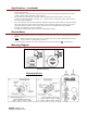
Mounting Diagram
(Shown In Inches)
Mounting Options