Ultrasonic compact heat and heat/cooling energy meters WS.5.., WS.6.. Ultrasonic heat meters to measure flow and energy in hydronic heating or cooling circuits. ● ● ● Non-wearing due to non-moving parts Approved in accordance with EN 1434 and MID accuracy class 2 Compact meter with flow measuring section – WS.5.. made of high-tech plastic ● ● ● ● ● ● ● CE2N5372en 2021-04-06 – WS.6..
Use The heat (WSM5../WSM6..) and cooling energy meters (WSB5../WSB6..) and combined heat/cooling energy meters (WSN5../WSN6..) are measuring devices to physically acquire energy consumption. The device consists of a flow measuring section made of high-tech plastic (WS.5..) or brass (WS.6..), 2 ready connected temperature sensors, and an electronic unit which calculates the energy consumption from the flow and temperature differential. The compact meter WS..
M-bus communication (optional) The meter can be read out from a remote location via an M-bus master unit, if the meter uses M-bus communication. M-bus RF communication (optional) If the meter uses M-bus RF communication, it can be read out remotely. Tampering To open the device, the calibration seal at the top of the WS.. must be destroyed. Self diagnostics The meter continuously performs self-diagnostics, allowing it to detect a number of mounting or device errors and to display them.
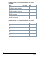
Pressure loss characteristic WS.5.. Nominal flow Mounting qp length m3/h mm Connecting thread Pressure loss at qp mbar Kv value at Δp = 1 bar m3/h Curve in the diagram 0.6 110 G¾ 75 2.2 A 1.5 110, 130 G ¾, G 1 135 4.1 B 2.5 130 G1 135 6.8 C The value can also be read graphically using the diagram as an alternative. A Pressure loss in mbar 1000 B C 250 100 10 0.
Pressure loss characteristic WS.6.. Nominal flow Mounting qp length m3/h mm Connecting thread Pressure loss at qp mbar Curve in the diagram G/DN 0.6 110, 190 G¾ 150 1.5 A 1.5 130, 190 G1 160 3.8 B 1.5 110 G ¾, 150 3.9 C 2.5 190 G1 210 5.3 D 2.5 130 G1 200 5.6 E A 1000 Pressure loss in mbar Kv value at Δp = 1 bar m3/h BC DE 250 100 10 0.1 1 10 Flow in m³/h Display The WS.. has a large, easy-to-read LCD with 7 digits to display different values (e.g.
The arrow icons mark the display of a stored value of the previous year or previous month. A calibrated value (e.g. energy) is marked on the display by a star symbol. The decimal places of displayed values are indicated by a frame. 1 2 3 4 1 Calibration seal 3 Optical interface 2 Display 4 Optical interface NOTICE The range of display and the displayed data may deviate from this description and certain button functions may be disabled, depending on the parameter settings on the meter.
21,0 K Temperature difference Mounting location (Here: Heat side, can be changed; optional) P hot Bd 1234 h Runtime totalizer Fd 123 h Error time Pd 1234 h Time with flow rate Monthly values LOOP 2 01.06.
01.--.-I 5-00 Monthly value (monthly set day) FW CrC 1234 Firmware version CRC code, part requiring calibration Other LOOP 4 17.11.11 Current date [TT.MM.JJ] 10.38.57 Current time of day [hh.mm.ss] ------- C Code entry for test/parameter operation Error codes The meter continuously performs self-diagnostics, allowing it to detect and display a number of mounting or device errors.
Monthly values The electronic unit stores the meter readings for energy, volume, missing time, and flow measuring time as well as the monthly maximum values of flow rate, power, temperature heat and cold side with their date stamp for up to 24 months on the set day of each month. The set day for previous monthly values can be parameterized. In addition, a second programmable monthly set day is available for 24 months – the day on which energy and volume are stored. Standard parameters The UH50..
Heat meter nominal flow 0.6 m3/h with flow measuring section made of high-tech plastic WSM5..
Heat meter nominal flow 2.5 m3/h with flow measuring section made of high-tech plastic WSM5..
Heat/cooling energy meter nominal flow 1.5 m3/h with flow measuring section made of high-tech plastic WSN5.. Options Order number Type Mounting length 110 mm, connecting thread G ¾", Battery life 11-years, M-bus S55561-F279 WSN515-BE Mounting length 110 mm, connecting thread G ¾", Battery life 11-years, M-bus RF S55561-F282 WSN515-FE Heat/cooling energy meter nominal flow 2.5 m3/h with flow measuring section made of high-tech plastic WSN5..
Mounting accessories only for meters with brass flow measuring sections: Accessories for WS.6.. Component Order number Type Sealing disk for thread G ¾" LYU:9060944002 9060944002 Sealing disk for thread G 1" LYU:9060944003 9060944003 Mounting set for sensor Ø 5.2x45 mm, consisting off: - 1x sensor fitting DS M10x1 mm, brass - 2x O-rings - 1x grooved pin LYU:WZT-FA WZT-FA Mounting accessories for both compact meter types: Accessories for WS.5../WS.6..
Adapter piece 110 mm G ¾" to 165 mm G ¾": 1x extension G ¾ B" to G ¾ B" 1x gasket G ¾" LYU:WZM-VE165 WZM-VE165 Adapter piece 110 mm G ¾" to 190 mm G 1": 2x extension G ¾ B" to G 1 B" 2x gaskets G 1" LYU:WZM-V190 WZM-V190 Sealing disk, copper, for protection pocket G LYU:9060948 ½" or adapter WZT-A12, Ø 27.9/ 21.2 mm x 1.
Spacer G 1", length 130 mm, incl.
Notes Mounting Flow measuring section The mounting orientation is optional, the mounting location (heat or cold side) must correspond to the meter type. On heat energy meters or combined heat/cooling energy meters, the mounting location of the cooling side corresponds to the return and the mounting location of the heating side to the flow . On cooling energy meters, the mounting location of the heating side corresponds to the return and the mounting location of the cooling side to the flow .
Mount the processor unit away from the flow measuring section (e.g. on the wall). Make sure that condensation cannot run along the connected lines, entering the processor unit (forming a loop downward). Permissible mounting position when metering cooling energy: 1 1 Transducer cover (only applies to WS.6..) Processor unit The ambient temperature of the processor unit cannot exceed 55 °C. Avoid direct sunlight. Ensure that no water can enter the processor unit at the mounting location.
Wall mounting Wall adapter (view from above) Wall adapter (side view) Maximal screw head height (if using the wall bracket) Maintenance The meters are maintenance-free. Observe all national calibration regulations. Disposal The device is considered an electronic device for disposal in accordance with the European Guidelines and may not be disposed of as domestic garbage. ● Dispose of the device through channels provided for this purpose.
Technical data Processor unit Power supply Battery type Lithium battery (cannot be replaced) Battery voltage 3.6 V Battery life 6 or 11 years Function data Measuring range 0…180 °C Range of temperature differential ΔΘ 3 ... 80 K Temperature response threshold 0.2 K Thermal coefficient Shifting compensated Temperature-measuring error without sensor (0.5 + ΔΘmin./ΔΘ) %, Max. 1.5% at ΔΘ = 3 K Temperature sensor Sensing element Pt500 Type Ø 5.
Function data ● Mounting length 130 mm Δp 2.2 1) / 1.5 2) Flow rate at Δp = 1 bar, Kv, m3/h 4.11) / 3.9 2) Mounting position 6.81) / 5.6 2) Any 1) Plastic flow measuring section Brass flow measuring section 2) Communication Optical interface ● Basic design ● Protocol Similar to EN 62056-21 Per EN 13757-2 / -3 M-bus wired interface Option ● Voltage Vmax. 50 V ● Power consumption 1 M-bus load ● Address Primary or secondary ● Baud rate 300 or 2400 baud ● Max.
Housing type Protection class IP class ● Processor unit ● Flow measuring section III IP54 WS.5..: IP65 WSM6..: IP54 WSB6../WSN6..: IP65 Ambient conditions Transportati Storage Operation EN 60721-3-3 on EN 60721-3-1 EN 60721-3-2 Climatic conditions Class A Class A Class A Temperature 5...55 °C -20...60 °C -20...60 °C Humidity <93% r.h. at 25 °C (noncondensing) <93% r.h. at 25 °C (noncondensing) <93% r.h. at 25 °C (noncondensing) Mechanical conditions Class M1 Class M1 Class M1 Max.
Housing colors Cover Bottom section RAL 9006 RAL 9002 Weight Device packed complete with inserts *) WSM506..: 0.52 kg WSM515..: 0.52 kg WSM525..: 0.56 kg WS.606..: 0.80 kg WS.615..: 0.76 kg WS.625..: 0.84 kg Documents can be downloaded at http://www.siemens.com/bt/download.
Connection diagram For meters with M-bus communication 1 Brown / white Dimensions WS.5..
WS.6.. Dimensions in mm Issued by Siemens Switzerland Ltd Smart Infrastructure Global Headquarters Theilerstrasse 1a CH-6300 Zug +41 58 724 2424 www.siemens.com/buildingtechnologies Document ID CE2N5372en Edition 2021-04-06 © Siemens Switzerland Ltd, 2012 Technical specifications and availability subject to change without notice.