
User Manual


3
Smart Infrastructure
CE2N5372en
2021-04-
06
M-bus communication (optional)
The meter can be read out from a remote location via an M-bus master unit, if the meter us-
es M-bus communication.
M-bus RF communication (optional)
If the meter uses M-bus RF communication, it can be read out remotely.
Tampering
To open the device, the calibration seal at the top of the WS.. must be destroyed.
Self diagnostics
The meter continuously performs self-diagnostics, allowing it to detect a number of mounting
or device errors and to display them.
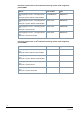
Technical design
The diagram below shows the typical accuracy of the WSM5.. / WSM6.. compared to the er-
ror limits per EN 1434 class 2.
Metering accuracy as per EN 1434
Key:
EN 1434, class 3
EN 1434, class 2
WS.5.. / WS.6.. typical (EN 1434, ½ class 2)
The pressure loss in a flow sensor is indicated as nominal flow q
p
.
Actual pressure loss at the indicated flow can be calculated using the K
v
value, which indi-
cates flow at 1 bar differential pressure:
Δp = 1 bar x (Q / K
v
)
2
Δp = Pressure loss in bar
Q = Flow in m
3
/ h
K
v
= K
v
– Value at Δp = 1 bar
-
10
-8
-6
-4
-2
0
2
4
6
8
10
1 10 100
R
e
l
a
t
i
v
e
e
r
r
o
r
s
[
%
]
Flow [%/qp]
Error limit per EN 1434