Ultrasonic compact heat and heat/cooling energy meters WS.5.., WS.6.. Ultrasonic heat meters to measure flow and energy in hydronic heating or cooling circuits. ● ● ● ● ● ● ● ● ● ● CE2N5372en 2020-08-18 Non-wearing due to non-moving parts Approved in accordance with EN 1434 and MID accuracy class 2 Compact meter with flow measuring section – WS.5.. made of high-tech plastic – WS.6..
Use The heat (WSM5../WSM6..) and cooling energy meters (WSB5../WSB6..) and combined heat/cooling energy meters (WSN5../WSN6..) are measuring devices to physically acquire energy consumption. The device consists of a flow measuring section made of high-tech plastic (WS.5..) or brass (WS.6..), 2 ready connected temperature sensors, and an electronic unit which calculates the energy consumption from the flow and temperature differential. The compact meter WS..
Processor unit A common electronic unit applies to all flow variables. Optical communication interface The meter is equipped with an optical communication interface which facilitates readout and configuration on site with the help of the optical read head WZR-OP-USP and matching UltraAssist software. M-bus communication (optional) The meter can be read out from a remote location via an M-bus master unit, if the meter uses M-bus communication.
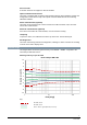
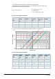
The pressure loss in a flow sensor is indicated as nominal flow qp. Actual pressure loss at the indicated flow can be calculated using the Kv value, which indicates flow at 1 bar differential pressure: Δp = Pressure loss in bar Δp = 1 bar x (Q / Kv) 2 Q = Flow in m3 / h Kv = Kv – Value at Δp = 1 bar Pressure loss characteristic WS.5.. Nominal flow Mounting length qp m3/h mm Connecting thread Pressure loss at qp mbar Kv value at Δp = 1 bar m3/h Curve in the diagram 0.6 110 G¾ 75 2.2 A 1.
A Pressure loss in mbar 1000 BC DE 250 100 10 0.1 1 10 Flow in m³/h Display The WS.. has a large, easy-to-read LCD with 7 digits to display different values (e.g. energy or flow). This new type of dynamic display enables users to identify positive flow at a glance. Icons for previous year values and previous month values support the easy-to-understand display concept.
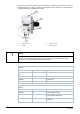
The arrow icons mark the display of a stored value of the previous year or previous month. A calibrated value (e.g. energy) is marked on the display by a star symbol. The decimal places of displayed values are indicated by a frame. 1 2 3 4 1 Calibration seal 3 Optical interface 2 Display 4 Optical interface NOTICE The range of display and the displayed data may deviate from this description and certain button functions may be disabled, depending on the parameter settings on the meter.
21,0 K Temperature difference Mounting location (Here: Heat side, can be changed; optional) P hot Bd 1234 h Runtime totalizer Fd 123 h Error time Pd 1234 h Time with flow rate Monthly values LOOP 2 01.06.
Other LOOP 4 17.11.11 Current date [TT.MM.JJ] 10.38.57 Current time of day [hh.mm.ss] ------- C Code entry for test/parameter operation Error codes The meter continuously performs self-diagnostics, allowing it to detect and display a number of mounting or device errors.
Data telegram for mobile data acquisition on WSM5xx-FE and WSN5xx-FE The following data is factory set to acquire data (send interval 120 seconds at a battery life of 11 years): ● Device time ● Current energy amount ● Current energy amount for incorrect installation / in the cooling registers ● Previous year value storage time ● Prev.
Heat meter nominal flow 1.5 m3/h with flow measuring section made of high-tech plastic, WSM5..
Heat/cooling energy meter nominal flow 1.5 m3/h with flow measuring section made of high-tech plastic WSN5.. Options Order number Type Mounting length 110 mm, connecting thread G ¾", Battery life 11-years, M-bus S55561-F279 WSN515-BE Mounting length 110 mm, connecting thread G ¾", Battery life 11-years, M-bus RF S55561-F282 WSN515-FE Heat/cooling energy meter nominal flow 2.5 m3/h with flow measuring section made of high-tech plastic WSN5..
Mounting accessories for both compact meter types: Accessories for WS.5../WS.6..
Smart Infrastructure Ball valve R ½" to install a DS sensor M10 x 1 mm, length = 28 mm, max. 130°C, PN 25 S55563-F104 WZT-K12 Ball valve R ¾" to install a DS sensor M10 x 1 mm, length = 28 mm, max. 130°C, PN 25 S55563-F120 WZT-K34 Ball valve R 1" to install a DS sensor M10 x 1 S55563-F119 mm, length = 28 mm, max.
Programming accessories Component Order number Type Optical read head with USB plug for PC interface LYU:WZR-OP-USB WZR-OP-USB Readout and configuration software: - UltraAssist Download - Ordering Please specify the quantity, order number, and type when ordering. Scope of delivery The ultrasonic meter is supplied complete with Mounting Instructions in different languages, an adapter kit, 2 gaskets and a seal.
Mount the flow measuring section between 2 shutoff valves with the arrow pointing in the direction of flow. The sensors must be mounted in the same water circuit as the flow measuring section (observe mixing). Do not separate, shorten, or extend the lines. The sensors can be fitted in T-pieces or ball valves, or can be immersed, either directly or in pockets (observe all national regulations). In any case, the end of the sensors’ probe must extend to at least the pipe center.
To fit the processor unit to the wall, remove it from the flow measuring section and screw the adapter plate to the wall and slide the processor unit to the adapter base, snapping into place. NOTICE WS.5..: The adapter plate cannot be removed. The wall adapter must be ordered separately as an accessory. WS.6..: The adapter plate can be removed from the flow measuring section.
Disposal The device is considered an electronic device for disposal in accordance with the European Guidelines and may not be disposed of as domestic garbage. ● Dispose of the device through channels provided for this purpose. ● Comply with all local and currently applicable laws and regulations. ● Dispose of empty batteries in designated collection points. Warranty service The application-related technical data is only guaranteed together with the products mentioned in this data sheet.
Technical data Processor unit Power supply Battery type Lithium battery (cannot be replaced) Battery voltage 3.6 V Battery life 6 or 11 years Function data Measuring range 0…180 °C Range of temperature differential ΔΘ 3 ... 80 K Temperature response threshold 0.2 K Thermal coefficient Shifting compensated Temperature-measuring error without sensor (0.5 + ΔΘmin./ΔΘ) %, Max. 1.5% at ΔΘ = 3 K Temperature sensor Sensing element Pt500 Type Ø 5.
Communication Optical interface ● Basic design ● Protocol Similar to EN 62056-21 Per EN 13757-2 / -3 M-bus wired interface Option ● Voltage Vmax. 50 V ● Power consumption 1 M-bus load ● Address Primary or secondary ● Baud rate 300 or 2400 baud ● Max. permissible reading frequency 1x per minute ● Protocol As per EN 13757-2/-3, EN 1434-3 ● Connection cable length and cross section 1.5 m, 2x AWG24/0.2 mm2 M-bus RF interface Option ● Transmission frequency 868.95 MHz (868.90 … 869.
Standards, guidelines Product standards DIN EN 1434-x (heat meters) EU conformity (CE) CE2T5372xx *) RCM Conformity CE2T5372en_C1 *) Environmental compatibility The product environmental declaration CE2E5372en *) contains data on environmentally compatible product design and assessments (RoHS compliance, material composition, packaging, environmental benefit, and disposal).
Connection diagram For meters with M-bus communication 1 Brown / white Dimensions WS.5..
WS.6.. Dimensions in mm Issued by Siemens Switzerland Ltd Smart Infrastructure Global Headquarters Theilerstrasse 1a CH-6300 Zug Tel. +41 58 724 2424 www.siemens.com/buildingtechnologies 22 Smart Infrastructure Document ID CE2N5372en Edition 2020-08-18 © Siemens Switzerland Ltd, 2012 Technical specifications and availability subject to change without notice.