CHSL4010 CHSL4011 Large Camera Housing Installation Guide Building Technologies Fire Safety & Security Products
Data and design subject to change without notice. / Supply subject to availability. © 2008 Copyright by Siemens Building Technologies We reserve all rights in this document and in the subject thereof.
Contents 1 1.1 1.2 1.3 1.4 Safety .......................................................................................................5 Target group..............................................................................................5 General safety precautions .......................................................................5 Meaning of the signal words .....................................................................6 Meaning of the hazard symbols ...................................
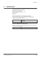
Safety 1 Safety 1.1 Target group The instructions in this document are designed only for the following target group. 1.2 Target readers Qualification Activity Condition of the product Installer Technical training for building or electrical installations. Installs the product, individual components of the product or replacement parts. Components of the product are not yet installed or need to be replaced or modified.
Safety 1.3 Meaning of the signal words The severity of a hazard is indicated by the following written warning notices. 1.4 Signal word Type of hazard CAUTION There is a risk of minor to medium injuries or damage to property IMPORTANT Malfunctioning may result Meaning of the hazard symbols The nature of the hazard is indicated by icons. Warning of a hazard 6 Siemens Building Technologies Fire Safety & Security Products 09.
EU Directives 2 EU Directives The product complies with the requirements of the following EU directives. The EU declaration of conformity is available from: Siemens Building Technologies Fire & Security Products GmbH & Co.
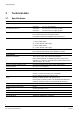
Technical data 3 Technical data 3.1 Specifications Nominal Voltage Fuse Rating (Fuse F1) Electrical Connections CHSL4010: 110 – 230 V AC, 50/60 Hz CHSL4011: 12 – 24 V AC, 50/60 Hz CHSL4010: 2 A 250 V AC 5 x 20 Type (T), HBC CHSL4011: 5 A 250 V AC 5 x 20 Type (T), HBC Main supply connections via fused PCB mounted terminal blocks. Use crimped ferrules when terminating cables. 6 way pillar terminal block available for user connections.
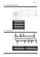
Technical data 3.2 Mechanical dimensions Fig. 1 3.3 Mechanical dimensions 1 168 mm 2 143 mm 3 82.5 mm 4 100 mm 5 155 mm 6 627 mm 7 609 mm 8 559 mm 9 596 mm 10 149 mm Key to Parts 1 2 3 4 10 9 Fig. 2 8 7 6 5 Key to Parts 1 Front End Cap 6 Cable Anchor 2 Housing Body 7 Terminal Board 3 Sunshield 8 Camera Mounting Plate 4 Rear End Cap 9 Demister Assembly 5 Cable Glands 10 Window 9 Siemens Building Technologies Fire Safety & Security Products 09.
Scope of delivery 4 Scope of delivery z Installation Guide z Camera fixing screw (1/4” BSW x ½” hex hd.) z Camera fixing screw (1/4” BSW x ¾” hex hd.) z 4 x M6x12 mm socket cap head screws z 4 x M6 washers z Spacer block (1.6 mm thick) z Spacer block (3 mm thick) z Spacer block (6.3 mm thick) z 3 mm (across flats) ALLEN key z Shoulder washer (to insulate screw from camera mounting plate) NOTE The complete assembly should be mounted and tested in the workshop prior to use on-site.
Mounting 5 Mounting 5.1 Adjusting the Sunshield 1. Firmly squeeze (A) the sides of the sunshield (See Fig. 3). 2. Slide (B) the sunshield to the required position. 3. Release the sunshield and it will remain in position. Fig. 3 5.2 Sunshield adjustment Accessing the inside of the Housing Enclosure 1. Using the ALLEN key provided, loosen but do not completely remove the 4 securing screws (A) (See Fig. 4). 2. Slide the housing cover forwards (B). 3.
Mounting 5.3 Mounting the Camera and Lens Assembly 1. With the housing cover slid forward or removed, slacken the Pozi Pan Head Screw, but do not remove (A) (see Fig. 5). 2. Push the plate to unclip it from the rail (B). 3. Pull back the plate to release it from the rail (C). 4. Secure the camera to the plate, as per the manufacturer’s instructions (screws suitable for most cameras are supplied with the housing).
Mounting 5.4 Mounting the Camera Housing Assembly The housing has a set of 4 x M6 x 10 mm deep tapped holes on a 101.6mm (4”) PCD for mounting the camera housing to a bracket. Ensure the screws used to mount the housing to a bracket do not bottom out in the mounting holes by being too long. 1. Screw the mounting bracket to the base of the unit (A) (see Fig. 6). 2. Secure the assembly following the bracket installation instructions. Fig.
Mounting 5.5 Connecting to the Power Supply IMPORTANT Please read the ‘Safety’ section on Page 5 before connecting to the Power Supply. IMPORTANT All wiring must be installed to local and national standards. Ensure all SELV and signal wiring is kept away from live parts and is suitably protected from live parts by double insulation. CAUTION A readily accessible all-pole disconnect device with at least 3 mm contact separation shall be incorporated in the building installation wiring.
Mounting Fig. 8 Terminal board connection details 1 Ancillary Connections Block 2 Fused Output 3 Earth (Gnd) 4 Input Supply Terminal 5 Fuse F1 2 A 250 V AC 5x20 Type (T), HBC for T462 5 A 250 V AC 5x20 Type (T), HBC for T463 6 Heater Output (pre-wired and connected through fuse F1) 15 Siemens Building Technologies Fire Safety & Security Products 09.
Maintenance and service 6 Maintenance and service The following maintenance guidelines should be observed. Cleaning Use only soap and water to clean the housing and pane - no abrasive solvents. Additional protection can be applied to the pane to reduce contamination and droplet formation from moisture or rain. Products from the automotive or cleaning industry which use nanotechnology to reduce surface energies and thus contamination and moisture build-up can be used for this purpose.
Issued by Siemens Building Technologies Fire & Security Products GmbH & Co. oHG D-76181 Karlsruhe www.buildingtechnologies.siemens.com Document no. A6V10087715 Edition 10.09.2008 © 2008 Copyright by Siemens Building Technologies Data and design subject to change without notice. Supply subject to availability.